3
To prevent electrical shock and/or equipment
damage, disconnect electric power to system, at
main fuse or circuit breaker box, until installation
is complete.
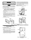
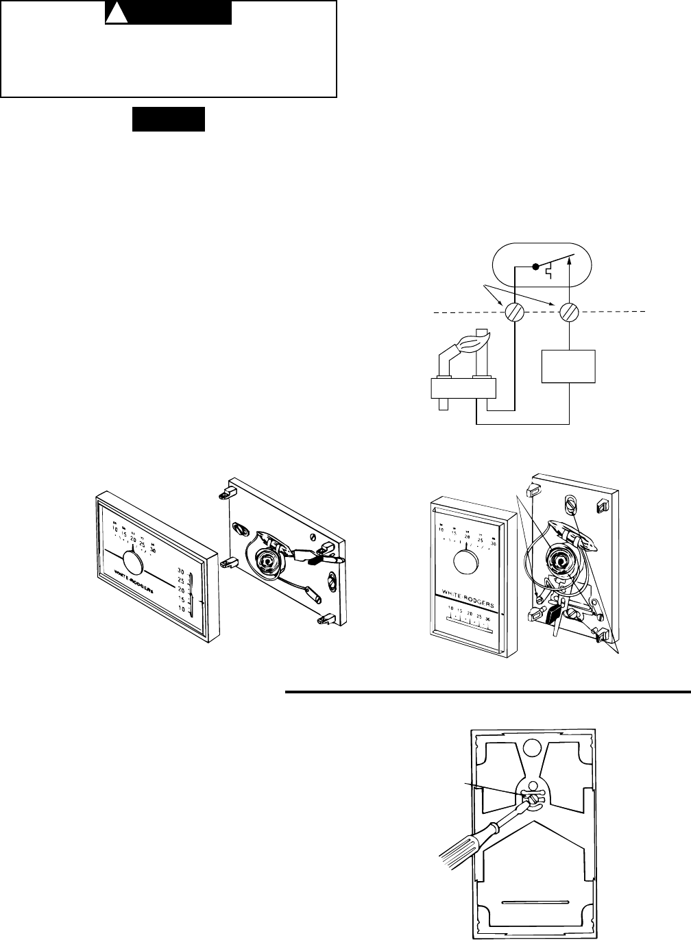
This typical wiring diagram shows only terminal identifica-
tion and wiring hook-up. Always refer to the wiring instruc-
tions provided by the equipment manufacturer for system
hook-up.
All wiring should be installed according to local and
national electrical codes and ordinances.
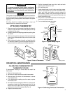
5. Position thermostat base over hole in wall and mark
mounting hole location on wall.
6. Drill mounting hole.
7. Fasten base loosely to wall using mounting screws.
Place a level against the top of the thermostat base,
adjust until level, and tighten mounting screws to
secure base. If holes in wall are too large and do not
allow you to tighten the mounting screws securely, use
plastic expansion plugs.
8. Snap cover on the thermostat base and set tempera-
ture lever to desired setpoint.
9. Turn on electrical power to system.
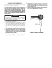
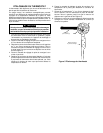
Figure 4. Calibrating Thermostat Thermometer
CALIBRATING THERMOMETER ON
THERMOSTAT COVER
If thermometer reading on cover does not match the
thermostat:
1. Remove thermostat cover.
2. Set cover on table near an accurate thermometer.
3. Allow at least 10 minutes for thermometer to sense
room temperature.
4. If the thermometer readings are the same, replace
thermostat cover.
5. If the thermometer readings are different, insert a small
screwdriver blade into the thermometer shaft in the
back of the cover. Adjust until the cover thermometer
matches the other thermometer (See Fig. 4).
6. Replace thermostat cover.
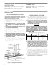
Figure 3. Parts of Thermostat
Figure 2. Typical Wiring Diagram
THERMOSTAT
BASE
COVER
COVER
THERMOSTAT
BASE
Mounting screws
Terminal
Screws
Heating
System
THERMOSTAT
SYSTEM
Thermostat
Switch
Power Generator
Heat
Pilot Flame
Thermometer
Adjustment
Back Side of
Thermostat Cover
OPERATION & MAINTENANCE
Terminal
Screws
ATTACHING THERMOSTAT
1. Remove cover from thermostat by gripping the base in
one hand. Use the other hand to pull gently at the top
or bottom of the cover.
2. Carefully remove the shipping protective packing from
the switch.
3. Pull wires through the opening in the thermostat base
and connect wires beneath the terminal screws (see
Fig. 2 & 3).
4. Push excess wiring back into wall and plug hole with
fire resistant material (such as fiberglass insulation) to
prevent drafts from affecting thermostat operation.
CAUTION
!
NOTE


