


3
OPERATION
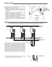
To set the thermostat, simply move the dial so that the
indicating line on the case points to the temperature at
which the contacts are to open.
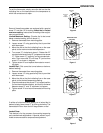
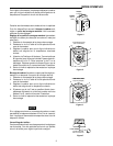
Some of these thermostats are equipped with a special
screw “C” and disk “B” for making locked dial or limited
maximum setting. Instructions for making either adjust-
ment are as follows:
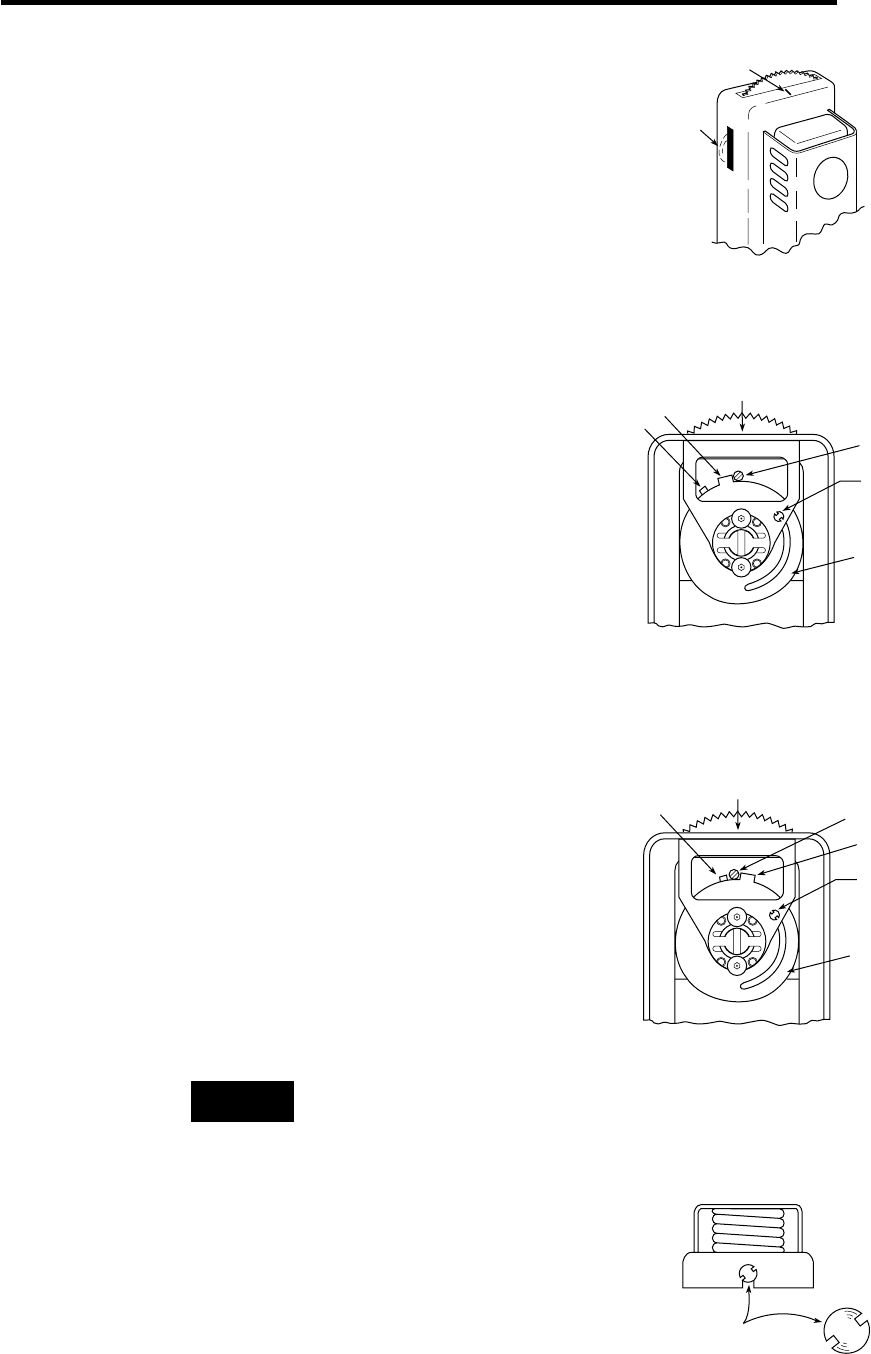
Limited Maximum Setting: (Permits dial to be turned
below a desired setting, but not above it.)
1. Remove thermostat from mounting plate.
2. Loosen screw “A” using special key that is provided
with thermostat.
3. Move the dial so that the indicating line on the case
points to the maximum desired temperature.
4. Turn screw “C” clockwise to lower it. Rotate disk “B”
counterclockwise until stop “D” just passes over screw
“C”. Raise screw “C” again by turning counterclock-
wise. Then move disk “B” until stop “D” just touches
screw “C” as shown in diagram.
5. Tighten screw “A” and replace thermostat on mount-
ing plate.
Locked Dial: (Dial cannot be turned above or below a
desired setting.)
1. Remove thermostat from mounting plate.
2. Loosen screw “A” using special key that is provided
with thermostat.
3. Move the dial so that the indicating line on the case
points to the desired temperature setting.
4. Check to make sure that screw “C” is in raised position
(full counterclockwise rotation), and that it is centered
between stops “D” and “E“ as shown in diagram.
5. Tighten screw “A” and return thermostat to mounting
plate.
If neither a limited maximum setting nor a locked dial is
desired, simply lower screw “C” by turning clockwise. The
thermostat will then have the full range shown on dial.
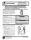
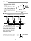
Locked Case:
This feature is for the purpose of preventing tampering
and unauthorized adjustments. A special wrench is pro-
vided to remove case for temperature adjustment.
NOTE
LOCK SCREW
AT BOTTOM
OF CASE
Figure 7
E
D
C
A
B
INDICATING LINE
(ON CASE)
Figure 6
E
D
C
A
B
INDICATING LINE
(ON CASE)
Figure 5
S
70
60
80
Indicating
Line
Summer
Dial
Position
Figure 4