


2
INSTALLATION
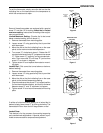
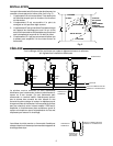
If the thermostat is used with unit heaters, the following
suggestions may help. (See Fig. 2).
1. Position “A” is good if it is sufficiently close to the unit
heater so that the return air to the heater flows over the
thermostat.
2. Position “B” is good if it is not necessary to make
frequent adjustments of the dial setting.
3. Position “C” is all right if it is sufficiently far from the
heater that air flowing over the thermostat is not much
above the average room temperature.
4. In general, position “D” is not advisable because the
post may prevent air from circulating over the thermo-
stat.
WIRING
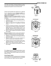
All wiring should be done in accordance with local and national electrical codes and ordinances.
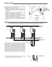
Diagram showing a single room thermostat controlling
several steam or hot water unit heaters. Any number of
unit heaters can be operated from one thermostat pro-
vided that the sum of the motor locked rotor currents or
the sum of the full load currents does not exceed the
electrical rating of the thermostat. The Type 11B09
Reverse-acting Surface Hot Water Control is used to
prevent operation of the fans when the steam is off or
when the water temperature is too low for proper heating.
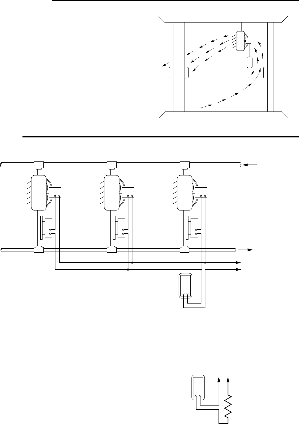
The diagram at the right shows a heavy duty line voltage
room thermostat controlling an electric heater.
A
C
D
B
CEILING
POST PARTITION
WALL OR POST
DIRECTLY BEHIND
UNIT
RETURN AIR
FLOOR
UNIT
Figure 2
TO LINE SWITCH
AND POWER SUPPLY
TYPE
11B09
TYPE
11B09
TYPE
11B09
ROOM
THERMOSTAT
ROOM
THERMOSTAT
TO LINE SWITCH
AND POWER SUPPLY
ELECTRIC HEATER
SUPPLY
RETURN