


3
F
F
T
T
V1
V2
1
2
3
4
56
4
56
4
56
4
56
1
2
3
452
6
1
2
3
452
6 1
2
3
452
6 1
2
3
452
6
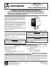
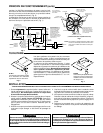
To prevent injuries from scalding always drain system
before unlatching valve assembly from body.
▼
▼
▼
▼
2-3/4" MINIMUM
CLEARANCE
2" MINIMUM
CLEARANCE
VALVE
HEAD
STEM
BODY
Fig. 5
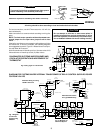
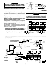
DIAGRAM FOR SYSTEMS WHERE BURNER AND
CIRCULATOR OPERATION IS INDEPENDENT OF
THERMOSTAT
Fig. 6 Using Type 1311 Zone Valve
T2
T1-V1
V2-L1
Z-L2
MUST BE N.E.C.
CLASS 1 WIRING
MUST BE
N.E.C. CLASS 1
WIRING
CIRCULATOR
MOTOR
1
2
3
{
TO ZONE
VALVES
TO 24 VOLT
GAS VALVE
YELLOW
HIGH LIMIT
TYPE 8A02A-1
CIRCULATOR MOTOR
HIGH LIMIT
RELAY CONTACTS
(24V OR 750 MV)
TRANSFORMER
RELAY COIL
WHITE
BLACK
WHITE
ORANGE
RELAY
CONTACTS
(LINE
VOLTAGE)
BURNER
MOTOR
IGNITION
TRANS.
TYPE 668 OIL
BURNER CONTROL
N
LINE
HOT
BLACK
TYPE 8A03A-2
ORANGE
V1
V2
TH
TH PG
PG
3
2
1
TYPE 8A03A-2
HIGH LIMIT
MUST BE N.E.C.
CLASS 1 WIRING
750 MV
GAS VALVE
1
2
3
}
TO ZONE VALVES
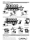
Alternate Wiring for using
750 Mv. Gas Valve
Alternate Connections
For Type 8A02A Relay
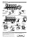
Fig. 7 Diagram
for Oil-fired
System using
8A03A-2
24 VAC
GAS VALVE
HIGH LIMIT
1
3
MUST BE N.E.C.
CLASS 1 WIRING
Fig. 7a Diagram for
Gas-Fired System
All wiring should be done according to local and national electrical codes
Do not attempt to wire two or more zone valves in
parallel to operate from a single thermostat. (If valves
are wired in parallel, the motors may run continuously,
due to feedback between the motor holding circuits.)
For best connections, use #18 Thermostat wire. #16 will also
work satisfactorily.
Make connections to screw terminals according to wiring dia-
gram.
NOTE: To check motor operation without thermostat con-
nected, jumper 4 to 5 to open valve; jumper 5 to 6 to close
valve.
If the boiler manufacturer recommends a wiring diagram, follow
his instructions. If none are available, the following diagrams
show suggested circuits for Type 1311 Water Valves in conjunc-
tion with other W-R controls.
A 40 VA transformer will handle up to four (4) water valves. A 20
VA transformer will handle up to two (2) water valves.
Clearances required for assembling valve head to valve body.
4
56
4
56
4
56
4
56
4
56
1
2
3
452
6
1
2
3
452
6
1
2
3
452
61
2
3
452
61
2
3
452
6
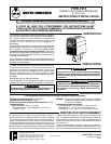
ADDITIONAL
ZONES
HOT
LINE
N
TRANSFORMER
DIAGRAM FOR SYSTEMS WHERE INTERNAL TRANSFORMER OF RELAY CONTROL SUPPLIES POWER
FOR ZONE VALVES
WIRING
TYPE 956
FLAME DETECTOR
HOT
LINE
N
750 MV
POWER
GENERATOR
CAUTION
!
CAUTION
!