


2
PRINCIPLE OF OPERATION (Continued)
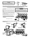
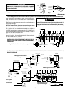
When thermostat is satisfied, the valve motor is again ener-
gized. Just after the valve starts to close, side “A” of motor switch
makes with holding contact providing a holding circuit. The side
“B” of motor switch opens (breaking auxiliary circuit), and side
“A” of motor switch makes with contact “4” then breaks the
holding circuit stopping the valve in the closed position. (Fig. 2)
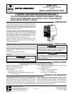
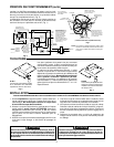
The contact arrangement is constructed so that when the shaft
of the motor revolves 90° a new set of stationary contacts makes
while the old set breaks. (Fig. 1)
NOTE: To check motor operation without thermostat
connected, jumper 4 to 5 to open valve; jumper
5 to 6 to close valve.
MOTOR SHAFT:
Revolves in 90° intervals
with each thermostat cycle.
STATIONARY CONTACTS
(TERMINALS 2 & 3)
STATIONARY CONTACTS
(TERMINALS 2 , 6 & COM.)
JUMPER WIRES
NOTE: INTERNAL PARTS AND
WIRING OF WATER VALVE.
COMMON
2
6
4
3
2
2
ROTATING BOARDS:
Each Board makes/breaks
1 set of contacts with each
90° revolution of motor
shaft on thermostat
demand.
▼
▼
▼
▼
▼
▼
▼
▼
▼
▼
▼
▼
▼
▼
▼
Use only silicone grease, water, or soap suds on O-ring
or Valve Body to facilitate assembly. Use of vaseline or
any petroleum grease or oil will cause O-ring to deterio-
rate.
Be sure that bayonet lock securely latches mounting
plate to body. Failure to do so could allow valve head
to separate from body and result in scalding injuries
and/or water damage.
1. Remove body assembly only from shipping carton. Valve
head and stem should be left in carton at this time for
protective purposes. Do not assemble head to body before
attaching body into line.
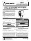
2. Mount the valve body in the line in any desired position
except upside down. CAUTION: Provide the necessary
clearances for turning valve head sideways when assem-
bling it to valve body (see fig. 3). Note that terminal end of
valve head requires more clearance.
3. Be sure that any excess solder, flux, or other foreign matter
is thoroughly removed from the valve bore.
4. With valve body mounted in the line, remove the head
assembly from the carton, and carefully wipe stem with a soft
cloth to remove any dust or grit.
5. The valve head may now be assembled to the valve body.
With valve head positioned as shown in figure 5, insert valve
stem into valve bore, push downward, and turn valve head
until it locks to valve body.
6. Support piping with a pipe hanger on each side of valve. The
valve is now ready to be wired.
ALL GUARANTEES ARE VOID IF THE VALVE IS NOT ASSEMBLED ACCORDING TO THESE INSTRUCTIONS.
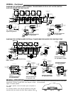
INSTALLATION
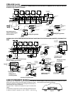
The two most commonly used piping systems are
shown below. Plan 1 is popular for new installations,
while plan 2 is frequently used for converting two-pipe
systems.
This valve does not seal completely. A small amount of
leakage through valve is permitted. The amount de-
pends on valve size and pressure differential across
closed valve. Do not use if your application requires
complete seal off. Maximum leakage at rated differen-
tial is two, four or six gal. per hour for 3/4", 1" or 1-1/4"
valves, respectively.
729
PLAN 1
Water valves installed at the boiler
header to provide a separate sup-
ply to each zone.
PLAN 2
A common main supplies all
zones, with a water valve installed
on the riser to each zone.
Fig. 3
Fig. 4
PIPING
▼
TRANSFORMER
INTERNAL
WIRING
EXTERNAL
WIRING
MOTOR
ANTIC.
SATISFIED
CALL FOR
HEAT
HOLDING
CONTACT
SIDE “A”
OPEN
POSITION
WATER VALVE
THERMOSTAT
TO AUXILIARY CIRCUIT
FOR OPERATING BURNER
AND/OR CIRCULATOR.
(NOTE: IF SAME TRANS-
FORMER POWERS BOTH
THE AUXILIARY CIRCUIT
AND THE WATER VALVE,
CONNECT AUXILIARY CIR-
CUIT TO TERMINALS 1 AND
3 INSTEAD OF 2 AND 3.)
SIDE “B”
OPEN
POSITION
2
3
6
5
4
LINE
▼
▼
▼
▼
▼
▼
▼
CLOSED
POSITION
SIDE “A” OF
MOTOR SWITCH
SIDE “B” OF
MOTOR SWITCH
▼
1
4
6
5
STATIONARY CONTACTS
(TERMINALS 2, 4 & COM.)
(Valve is shown in the open position)
Fig. 1
Fig. 2
SCHEMATIC OF VALVE
CAUTION
!
CAUTION
!