


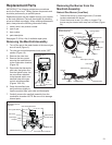
23
1. Check the door gasket for damage or imbedded debris
prior to installation.
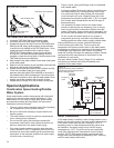
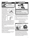
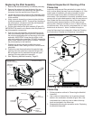
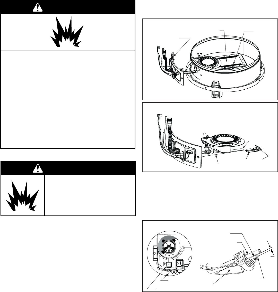
Figure 28A
Combustion Chamber
Door Gasket
Bracket
Flame-trap
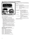
Figure 28B
Manifold Assembly Close-up
Close-up inside view of
the combustion chamber.
Manifold Tube
Bracket
Tab
Slot
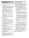
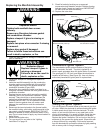
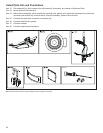
Piezoelectric Igniter System
The piezoelectric igniter system consists of the igniter
button, electrode, and wire. The pilot is ignited by an
electric spark generated when the igniter button is pressed.
The spark gap of 0.125 inch is set when the electrode is
installed at the factory. (See Figure 29). Use only factory
authorized piezoelectric igniter parts for replacement.
Testing the Igniter System
Turn off the gas to the water heater at the manual gas shut-
off valve. Watch the electrode tip while activating the igniter.
A visible spark should jump from the electrode. To avoid
shock, do not touch the burner or any metal part on the
pilot or pilot assembly. If no spark is visible, check the wire
connections and make sure the electrode is not broken.
Replace the igniter if defective. Dirt and rust on the pilot or
electrode tip can prevent the igniter spark. Wipe clean with
a damp cloth and dry completely. Rust can be removed
from the electrode tip and metal surfaces by lightly sanding
with an emery cloth or fine grit sandpaper.
Replacing the Manifold Assembly
2. Inspect the viewport for damage and replace as
required.
3. Insert the manifold assembly into the combustion
chamber making sure that the tab of the manifold
tube engages in the slot of the bracket inside the
combustion chamber (Figure 28B).
4. Inspect the door gasket and make sure there is no
fiberglass insulation between the door gasket and the
combustion chamber.
5. Replace the two screws which secure the manifold
assembly door to the combustion chamber. Tighten
securely. There should be no space between the
gasket part of the manifold door and combustion
chamber. IMPORTANT: Do not operate the water
heater if the door gasket does not create a seal
between the manifold door and the combustion
chamber.
6. Reconnect the two wire leads to the thermal switch,
the manifold tubing, pilot tubing, and thermopile to the
gas control valve/thermostat. IMPORTANT: DO NOT
attempt to disable or modify the thermal switch in any
way. Do not cross-thread or apply any thread sealant to
these fittings.
7. Reconnect the igniter wire.
8. Turn gas supply on and refer to the “Lighting
Instructions” on page 16.
Explosion Hazard
Replace viewport if glass is
missing or damaged.
Failure to do so can result in
death, explosion or fire.
WARNING
Explosion Hazard
Tighten both manifold door screws
securely.
Remove any fiberglass between gasket
and combustion chamber.
Replace viewport if glass is missing or
damaged.
Replace two piece wire connector if missing
or removed.
Replace door gasket if damaged.
Failure to follow these instructions can
result in death, explosion, or fire.
WARNING
9. Check for leaks by brushing on an approved
noncorrosive leak detection solution. Bubbles forming
indicate a leak. Correct any leak found. IMPORTANT:
All leaks must be fixed immediately.
10. Replace the outer door.
Figure 29
Natural Gas Igniter Assembly
Igniter Button
Pilot Bracket
Electrode
Thermopile
Pilot
.125”
Wire to Electrode
V
A
C
O
F
F
P
I
L
O
T
S
T
A
N
D
A
R
D
M
O
D
E
E
N
E
R
G
Y
S
M
A
R
T
M
O
D
E
N
O
R
M
A
L
1
2
0
°
N
O
R
M
A
L
1
2
0
°
H
O
T
1
5
0
°
L
O
W
L
O
W