


22
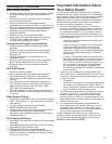
Replacing the Pilot Assembly
1. Remove the manifold assembly as directed previously.
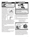
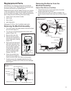
2. Remove the retainer clip from the back of the two
piece wire connector and remove the two piece wire
connector from the manifold door (Figure 25).
3. Locate and remove the screws on the underside of the
burner. Remove the screw securing the pilot assembly
to the manifold.
4. Using a wrench loosen the nut securing the pilot tube
to the pilot assembly. NOTE: To prevent any bending of
the pilot bracket, use pliers to hold the pilot assembly
bracket while loosening the pilot nut.
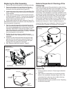
5. Pull the pilot tube from the pilot assembly (Figure 26).
IMPORTANT: Be careful not to bend or alter the position of
the pilot assembly components.
6. Push the new pilot assembly connectors through the
hole in the manifold door (See Figure 25). Reconnect
the pilot tube and tighten the nut securing it to the pilot
assembly. IMPORTANT: Keep the pilot orifice in the
pilot when making the connection. DO NOT operate the
water heater without the pilot orifice installed. Reattach
the pilot assembly to the manifold.
7. Reattach the burner and secure with the screws
removed earlier. Note: See figure 24 for correct burner
orientation.
8. Position the new thermopile wires through the lower
opening of the two piece wire connector (Figure 25).
Be sure igniter wire is positioned through the upper
opening of the two piece wire connector.
9. See “Replacing Manifold Assembly” Page 23.
Figure 25
Two Piece Wire
Connector Assembly
Thermopile
Connector
Two Piece
Wire Connector
Pilot Tube
Igniter
Wire
Retainer Clip
Burner and other fittings
not show for clarity.
Manifold Door
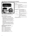
Figure 26
Pilot Assembly
Pilot
Assembly
Thermopile
Connector
Igniter Connector
Thermal
Switch
Connectors
Pilot
Thermopile
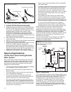
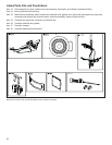
External Inspection & Cleaning of the
Flame-trap
Inspect the wrap around filter periodically to check for lint,
dust, or other debris that may have accumulated on it. If the
water heater is installed in an easily accessible location,
remove the wrap around filter and clean with soap and
warm water. If the installation is not easily accessible use a
vacuum with a brush attachement to clean the wrap around
filter. Rotate the filter around the base of the water heater,
vacuuming each exposed section until the wrap around
filter is clean. Although not likely to occur, if debris collects
on the flame-trap, use a vacuum, compressed air, or a soft
bristle brush to remove it. Note: If unable to inspect or
clean the flame trap from underneath, follow the “Cleaning
the Combustion Chamber and Flame-trap” instructions.
Cleaning the Combustion Chamber and
Flame-trap
1. Follow procedure outlined in “Removing the Manifold
Assembly”.
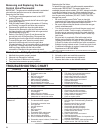
2. Use a vacuum cleaner/shop vac to remove all loose
debris in the combustion chamber (Figure 28A). Use
compressed air to clear any dust or debris that may
have accumulated in the flame-trap.
3. Reassemble following the procedure under “Replacing
the Manifold Assembly”.
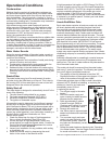
Figure 27
Flame-trap visual inspection
and cleaning
Flashlight
Mirror
Vacuum with
brush attachement