


23
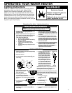
Replacing the Thermocouple
1. Remove the Burner Door Assembly as directed
previously.
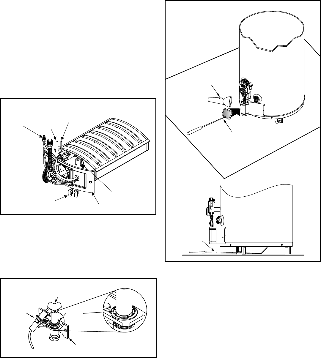
2. Remove the retainer clip from the back of the two
piece wire connector and remove the two piece wire
connector from the assembly (Figure 25).
3. Pull the thermocouple from the pilot assembly
(Figure 29).
IMPORTANT: Be careful not to bend or alter the position of
the pilot assembly components.
4. Push the new thermocouple through the holes in the
pilot bracket. Insert the thermocouple tube into the
holes provided in the pilot assembly until it clicks into
place. Leave a small straight section entering and
leaving the two piece wire connector section for easier
removal/service.
5. Position the new thermocouple through the opening of
the two piece wire connector (Figure 25). NOTE: The
pilot tube should be located at the top followed by the
igniter wire then the thermocouple.
6. See “Replacing the Burner Door Assembly” section.
Cleaning the Combustion Chamber
and Flame-trap
1. Follow procedure outlined in “Removing the Burner
Door Assembly” section.
2. Use a vacuum cleaner/shop vac to remove all loose
debris in the combustion chamber (Figure 28). Use
compressed air to clear any dust or debris that may
have accumulated in the flame-trap.
3. Reassemble following the procedure under the
“Replacing the Burner Door Assembly” section.
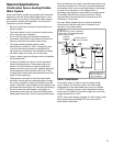
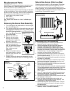
External Inspection & Cleaning of the
Flame-trap
Although not likely to occur, if debris collects on the flame-
trap, use a vacuum, compressed air, or a soft bristle brush
to remove it. NOTE: If unable to inspect or clean the flame-
trap from underneath, follow the “Cleaning the Combustion
Chamber and Flame-trap” section instructions.
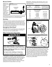
Mirror
Mirror
Flashlight
Figure 27
Flame-trap visual inspection
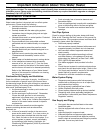
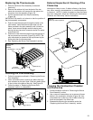
Cleaning the Pilot Assembly
1. Follow the procedure outlined in “Removing the Burner
Door Assembly”.
2. Use a soft bristle brush to remove any debris that may
have collected on the pilot. Note: Clean any debris found
in the air slots at the base of the pilot. See Figure 26.
3. Follow the steps in “Replacing the Burner Door
Assembly” section to reassemble.
Pilot
Igniter
Air Slots
Pilot Bracket
Figure 26
Pilot Assembly
Figure 25
Two Piece Wire
Connector
Assembly
Two Piece
Wire Connector
Thermocouple
Retainer Clip
Igniter
Wire
Manifold
Door
Pilot Tube