


4
n
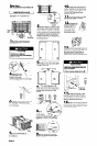
Insert the frame in the wall
opening. Square the level frame. Nail
frame securely to the wall studs.
Floor Damage
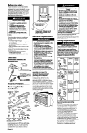
Remove air conditioner from carton
and place on cardboard.
Failure to do so may cause damage
to floor covering.
‘SCl&VS
20
n
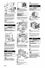
Attach front bv first
removing the two, #8 x 9?i mm (318”)
screws from base; then insert front tabs
into top of cabinet and swing front in
place. Attach bottom of front by
reinserting the two screws.
16
H Secure vertical and angle
THROUGH-THE-WALL
INSTALLATION
INSTRUCTIONS
. . . FOR SLIDE-OUT
CHASSIS MODEL ONLY.
supports together. Attach supporti? to
bottom of cabinet. But Do Not tiahten
bolts at this time. Attach wall rail to
angle supports. Slide each support
assembly toward house until wall rail is
positioned firmly against wall.
Note: If your house is constructed of
material that could be damaged by
wall-mounting support, fasten a board
between wall rail and house.
17
I Tighten bolts securely with a
11.1 mm (7/16”) socket and socket
wrench. Tighten angled support bolts
last so wall rail fits tightly against house,
It is the customer’s responsibility and
obligation to have this product installed
by a qualified technician familiar with
through-the-wall room air conditioner
installations.
apptoptlafe
header If required
frhl +
casing
,
w Loosen, but Do Not remove
grounding wire screw. Disconnect
grounding wire.
\ ‘,\\I II
louvers.
I I
Personal Injury/Product
Damage Hazard
Install window-lock bracket to prevent
air conditioner from falling out of
window.
Failure to do so could result in
personal injury or product damage.
thlcknes
6
w Pull on handles; slide air
conditioner out of cabinet and place
on cardboard.
7
n
Insert cabinet into wall opening.
The top of the cabinet should extend
12.7 mm (l/2”) into room. If there is trim,
the cabinet should extend 12.7 mm
(l/2”) in front of trim.
Frame construction
approptlafe
header If required
I
254 mm (10’3
drain
CUD
alternate
consftucffon
for plasfet
Provide 30 mm
(l-3/169
Property Damage
Check that air conditioner cabinet is
tilted to the outside so that water will
run to the outside.
Failure to do so may cause damage
to floor covering or wall.
provided, place
through hole in
cabinet rail as
&fe&an&efor \
I I I\\\\
power supply car
entry on leff dde
30 mm (l-3/16”)
clearance for
18
n
Insert window rail seal behind
1
Brick veneer construction
n
When using a wood, metal or
plastic molding, the finish frame should
line up with inside wall. If the plastered
wall is to be flush with the cabinet and
no molding is used, the finish frame must
be set 12.7 mm (l/2”) into the wall.
the top of the lower window sash and
against the glass of the upper window.
Place window-lock bracket on top of
lower window and against upper
window sash. Use a 2.4 mm (3/32”) drill
bit to drill a starter hole through the hole
in the bracket. Attach window-lock
bracket with wood screw. Seal small
openings around window with gum-
type sealer.
8
n
Place level inside cabinet on the
right side. There should be a tilt to the
outside of approximately one bubble.
Place the level on the left side and
check.
9
n
Use the insulation removed in
Step 2 to seal opening between cabinet
and frame.
10
n
Drill four holes on each side
Electrical Shock Hazard
Grounding wire from the air
conditioner must be connected to the
cabinet.
Failure to do so could result in
electrical shock.
and two through the top of the cabinet
into the frame. Use ten #lO x 25.4 mm
(1”) wood screws (not provided) to
attach cabinet to frame. Do Not
overtighten screws or cabinet will distort
and provide a poor air seal between
use 66
cm-
dimension
50.2 cm (19-3/4”)
(includes allowance
for 12.7 mm (l/2”)
flange on b&&m’ of
cabinet).
7
ul
6
Dimension
depends on
wall thickness
and type of
19
n
Inset-t air conditioner into
2
molding.
w Cut opening through
the wall. Remove insulation.
3
n
Use 25.4 mm (1”) or heavier
lumber for wood frame. Measure depth
of wall opening and frame.
Apply wood preservative to the outside
exposed surface.
cabinet. Reattach grounding wire to
grounding screw. Put excess grounding
wire between coil and grey beaded
foam.
Panel C