


Page 8 6104BAFG R06
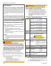
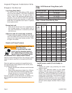
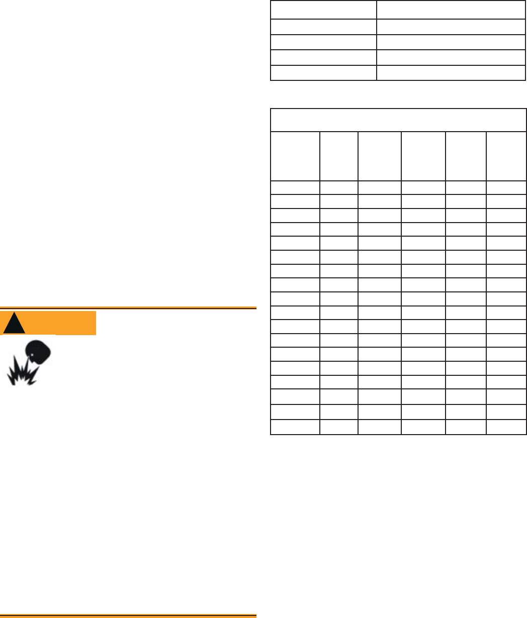
Table 4. AFG Reduced Firing Rates (with
LFRB)
Burner head type Low Firing Rate Baffl e installed
F0 up to 0.65 gph
F3 or L1 up to 0.85 gph
F4 or F6 up to 0.90 gph
V1 up to 1.00 gph
Prepare the Burner
Low Firing Rate Baff e
The AFG Low Firing Rate Baffl e (LFRB) reduces
the air fl ow and pressure. The LFRB is sometimes
used for fi ring rates under 1.00 gph as listed in
Table 4. Refer to the appliance manufacturer’s in-
structions. Do not omit the LFRB when specifi ed.
Omitting the baffl e when specifi ed or installing the
baffl e when not specifi ed could result in impaired
burner performance.
Burner fuel unit
Verify that the burner fuel unit is compatible with
the oil supply system. For more details, refer to
the pump manufacturer’s instructions provided
with the burner.
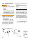
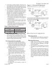
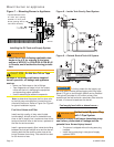
Attach air tube (if not already installed)
If using a fl ange and gasket, slide them onto the air
tube. Then attach the air tube to the burner chassis
using the four sheet metal screws provided. Refer
to Figure 4 for details.
y
Use only nozzles having the brand, fl ow rate (gph), spray
angle and pattern specifi ed by the appliance manufac-
turer.
Follow the appliance manufacturer’s specifi cations for
the required pump outlet pressure for the nozzle, since
this affects the fl ow rate.
Nozzle manufacturers calibrate nozzle fl ow rates
at 100 psig.
When pump pressures are higher than 100 psig,
the actual nozzle fl ow rate will be greater than
the gph stamped on the nozzle body. (Example:
A 1.00 gph nozzle at 140 psig = 1.18 gph)
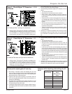
Securely tighten the nozzle (90 torque inch pounds). For
typical nozzle fl ow rates at various pressures refer to
Table 5.
y
y
Incorrect nozzles and fl ow rates
could result in impaired combus-
tion, under-fi ring, over-fi ring, soot-
ing, puff-back of hot gases, smoke
WARNING
!
Correct Nozzle and Flow
Rate Required
and potential fi re or asphyxiation hazards.
Nozzle and Pump Pressure
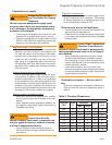
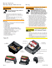
Install burner nozzle (if not already in-
stalled)
Remove the plastic plug protecting the nozzle
adapter threads
Place a 3/4” open-end wrench on the nozzle
adapter. Insert the nozzle into the adapter and fi n-
ger tighten. Finish tightening with a 5/8” open-end
wrench. Use care to avoid bending the burner head
support legs or electrodes. If you remove the head
to replace the nozzle (type “L1”/“L2” or “V1” heads),
carefully reconnect the head to the nozzle adapter,
making sure that the head support makes contact
with the nozzle adapter shoulder. Refer to Figure
5 or 6.
1.
2.
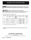
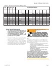
Nozzle f ow rate U. S. gallons per hour of No. 2 fuel oil when
pump pressure (psig) is:
Nozzle
size
(rated at
100 psig)
125
psi
140 psi 150 psi 175 psi 200 psi
0.40 0.45 0.47 0.49 0.53 0.56
0.50 0.56 0.59 0.61 0.66 0.71
0.60 0.67 0.71 0.74 0.79 0.85
0.65 0.73 0.77 0.80 0.86 0.92
0.75 0.84 0.89 0.92 0.99 1.06
0.85 0.95 1.01 1.04 1.13 1.20
0.90 1.01 1.07 1.10 1.19 1.27
1.00 1.12 1.18 1.23 1.32 1.41
1.10 1.23 1.30 1.35 1.46 1.56
1.20 1.34 1.42 1.47 1.59 1.70
1.25 1.39 1.48 1.53 1.65 1.77
1.35 1.51 1.60 1.65 1.79 1.91
1.50 1.68 1.77 1.84 1.98 2.12
1.65 1.84 1.95 2.02 2.18 2.33
1.75 1.96 2.07 2.14 2.32 2.48
2.00 2.24 2.37 2.45 2.65 2.83
2.25 2.52 2.66 2.76 2.98 -
2.50 2.80 2.96 - - -
Table 5. Nozzle Flow Rate by Size
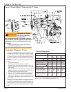
Inspect/Prepare Installation Site