


6104BAFG R06 Page 9
If the nozzle is already installed, remove the noz-
zle line assembly to verify that the nozzle size and
spray pattern are correct for the application (per ap-
pliance manufacturer’s information). Verify that the
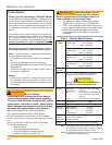
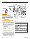
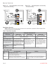
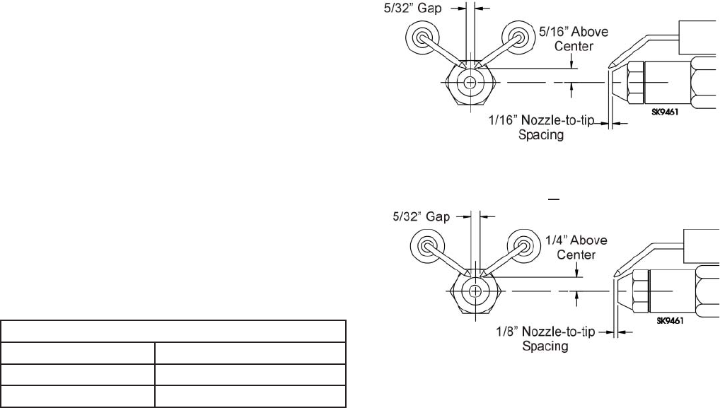
electrode tip settings comply with Figure 3.
If the nozzle is not installed, obtain a nozzle from
the manufacturer, having the capacity and spray
angle specifi ed in the appliance manufacturer’s in-
formation. For conversions or upgrades, when in-
formation is not available for the application:
Refer to Table 6 to select the mid-range nozzle
spray angle for the head type being used.
Fire the burner and make sure the combustion
is acceptable and the fl ame is not impinging on
chamber surfaces.
If a shorter fl ame is needed, select a wider spray
angle. If a longer fl ame is needed, select a nar-
rower spray angle.
Either hollow or solid spray patterns may be used.
If combustion results are not satisfactory with the
selected spray pattern, try the other pattern.
3.
4.
y
y
y
y
Mount burner on appliance
Mounting options
Bolt the burner to the appliance using the fac-
tory-mounted fl ange or an adjustable fl ange.
Mounting dimensions
When using the Beckett universal adjustable
fl ange, mount the air tube at a 2° downward
pitch unless otherwise specifi ed by the appli-
ance manufacturer.
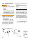
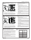
Verify that the air tube installed on the burner
provides the correct insertion depth. See Fig-
ure 7.
The end of the air tube should normally be ¼”
back from the inside wall of the combustion
chamber. Never allow the leading edge of the
head assembly to extend into the chamber, un-
less otherwise specifi ed by the heating appli-
ance manufacturer. Carefully measure the in-
sertion depth when using an adjustable fl ange.
Verify the insertion depth when using a welded
fl ange.
1.
1.
2.
3.
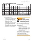
Figure 3. – Electrode Tip Adjustment
Recommended nozzle spray angles
“F” head 70° or 80° nozzle
“L1” & “L2” head 45°, 60°, or 70° nozzle
“V1” head 45°, 60°, or 70° nozzle
Table 6. Nozzle Spray Angles
Standard Dimensions for F, L1, and V1 Heads.
The Dimensions shown below are for use with L2 heads
and M series air tube combinations ending with an ‘N’ suf-
fi x (example: AFG70MDAQ
N)
Check/adjust electrodes
Check the electrode tip settings. Adjust if neces-
sary to comply with the dimensions shown in Fig-
ure 3. To adjust, loosen the electrode clamp screw
and slide/rotate electrodes as necessary. Securely
tighten the clamp screw when fi nished.
Servicing nozzle line assembly
Turn off power to burner before proceeding.
Disconnect oil connector tube from nozzle line.
Loosen the two screws securing igniter retain-
ing clips and rotate both clips to release igniter
baseplate. Then tilt igniter back on its hinge.
Remove splined nut.
“F” head air tube. - Remove nozzle line as-
sembly from burner, being careful not to
damage the electrodes or insulators while
handling. To ease removal of long assemblies
(over 9 inches), rotate assembly 180° from
installed position after pulling partially out of
tube.
“L1”, “L2”, and “V1” head air tubes. - Slide
nozzle line assembly forward (further into air
tube) so the head clears the venturi opening.
Then rotate the nozzle line assembly 90° so
the nozzle line end points up. Pull the nozzle
line assembly toward you and remove assem-
bly from burner.
To replace the nozzle assembly, reverse the
above steps.
1.
2.
3.
4.
5.
6.
7.
Prepare the Burner