


8
LGB-6 to LGB-23
Series 2 – Control Supplement
Part Number 550-141-916/1001
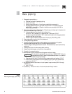
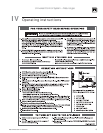
Wiring Procedure
1. Determine right or left electrical supply wiring.
2. Attach electrical junction box(es) to inside jacket end panel. Screws and nuts are provided.
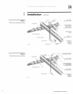
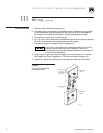
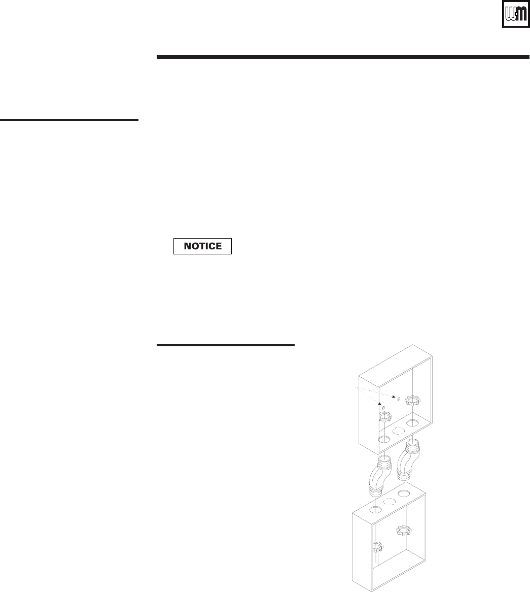
For dual base boilers, use offset nipples (provided) to connect junction boxes together,
then hang junction boxes by screwing top box to boiler jacket. See Figure 4, below.
3. Attach control transformer(s) to junction box(es).
4. Drill 1/8" hole in interior jacket panel midway between ignition control panel and left jacket
panel. Mount wire support clip using sheet metal screw (furnished).
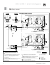
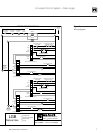
5. Complete wiring per wiring diagram, Figure 3 (pages 6 and 7).
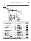
Figure 4
Junction box assembly
dual base boilers
“Hot” side of line voltage to boiler must be wired directly to limit circuit,
then fed to transformer primary(ies). Dual Base: “R” terminal of
secondaries are to supply power to bases independently of each other. Do
not wire “R” terminals together.
6. Install pilot proving and main flame proving ground connections as shown in Figures 1
and 2 (page 3) and Figure 3 (pages 6 and 7). Route wires through wire support clip.
7. Canada only - attach chain between junction box(es) and transformer with S-hooks.
Screw Holes
to Mount
Junction Box
to Jacket
Offset Nipples
(2)
Junction Box
Base 1
Junction Box
Base 2
911BGLr0
III Wiring – continued