CSD-1 control system — Natural gas
Part Number 550-110-677/0299
29
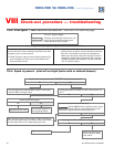
Check-out procedure — troubleshootingVIII
Set up microammeter to measure output current in flame sensor circuit as follows.
a. Detach sense lead from ignition control. Attach negative lead from microammeter to sense
terminal on ignition control.
b. Attach positive lead to sense wire from pilot assembly.
c. Disconnect main valve lead from terminal MV on ignition control.
d. Energize the system. Spark should ignite the pilot. As soon as pilot is burning,
microammeter should read at least 0.5 microamp for U.T. # 1003-615.
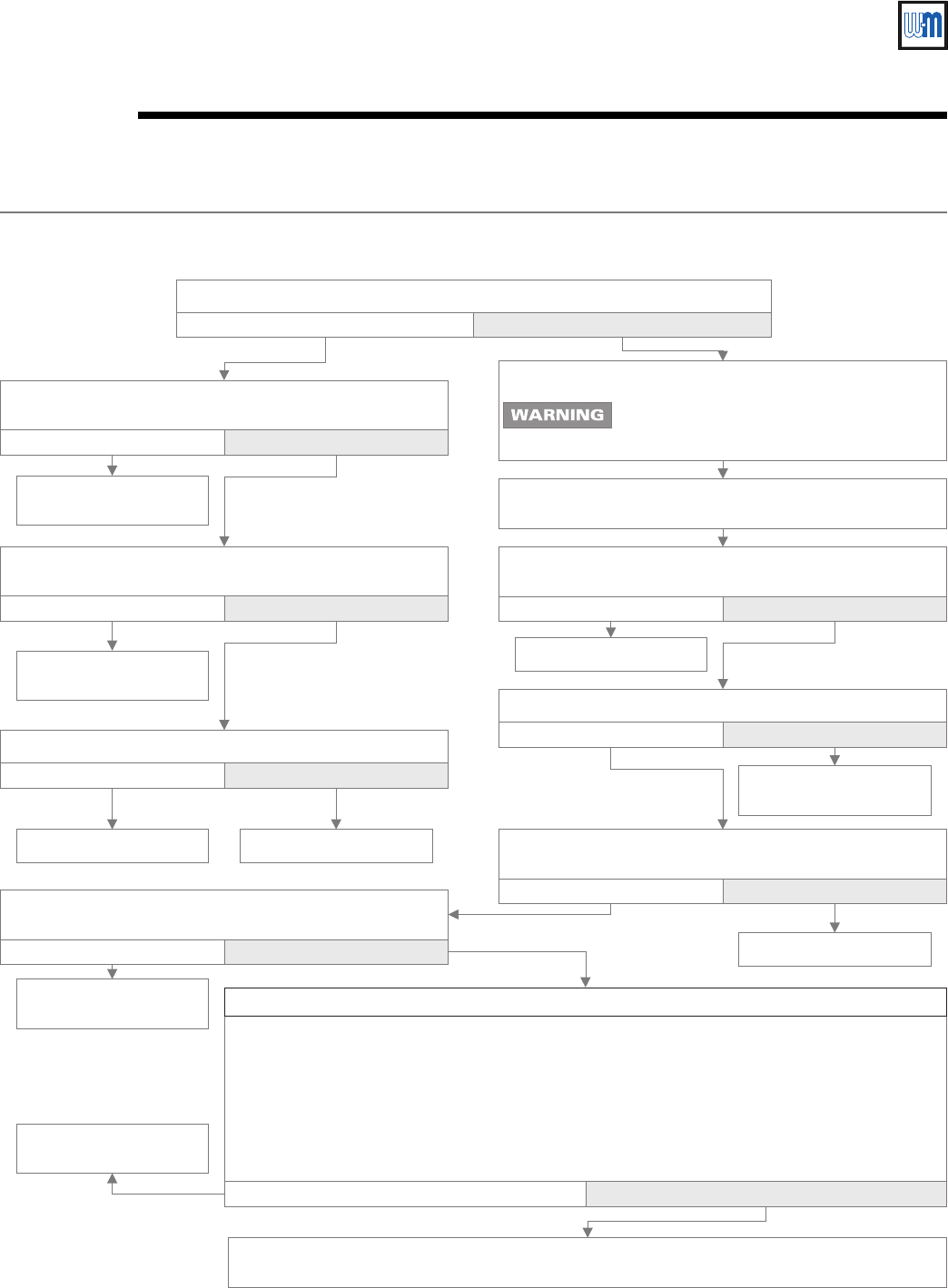
e. Is flame current signal less than the minimum specified in d above?
Does spark stay on for more than a few seconds after pilot is established?
Is 24VAC between terminals MV and MV/PV on ignition
control?
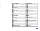
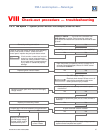
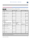
TS-3: Pilot lights — Main valve will not come on (boiler with or without damper)
No Ye s
Make sure sense wire is not wrapped around any pipe or
accessories.
No Ye s
Replace ignition control.
Retest.
Contact gas supplier to
correct.
Correct wiring. Retest. Replace valve. Retest.
Is main valve wiring secure at terminals?
No Ye s
Is inlet gas pressure at least 5.0" W.C. and not over 14"
W.C.?
No Ye s
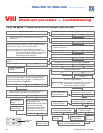
Is sense wire securely attached to sense terminal and pilot
assembly?
No Ye s
Correct and retest.
Is sensing probe ceramic cracked?
No Ye s
Replace pilot assembly.
Retest.
Is sense wire or sensing probe shorted out to metal
surface?
No Ye s
Correct and retest.
Check for continuity of sense wire and condition of
insulation.
NOT OK OK
Replace pilot assembly.
Retest.
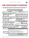
Does system have proper flame signal?
No Ye s
Check for proper gas pressure, clean pilot assembly, tight mechanical and electrical
connections. Also check for proper system grounding per following page.
Replace ignition control.
Retest.
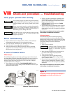
Turn OFF supply voltage.
Electrical shock hazard. Failure to turn off
power before proceeding could cause
severe personal injury or death.


