


EGH-105 to EGH-125 EGH-105 to EGH-125
EGH-105 to EGH-125 EGH-105 to EGH-125
EGH-105 to EGH-125 Control Supplement
Part Number 550-110-677/0299
8
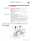
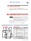
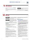
Gas pipingV
Size and connect gas supply piping per EGH Manual,
Section V.
The gas supply can enter from either the right or left
side of the jacket. Be sure the gas train is directed to the
correct side.
WiringVI
For your safety, turn off electrical
power supply before making any
electrical connections to avoid
possible shock hazard.
A strain relief bushing and adapter
must be used at each point where
wiring passes through the boiler
jacket or control cases to protect
wiring insulation.
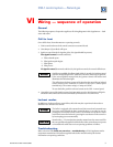
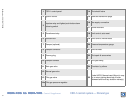
Assembly illustrations and wiring
diagrams
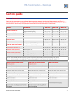
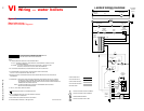
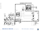
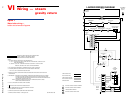
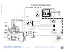
This Supplement contains three wiring diagrams and
associated assembly illustrations. Refer to the
following, as applicable:
• Water boilers —Figures 5 and 6
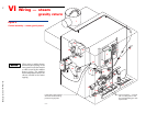
• Steam boilers, gravity return — Figures 7 and 8
• Steam boilers, pumped return — Figures 9 and 10
General
Refer to EGH Manual, Section VI for further
information.
All wiring must be installed in accordance with the
requirements of the National Electrical Code and any
additional national, state or local code requirements
having jurisdiction. All line voltage wiring external to
boiler jacket must be N.E.C. class 1.
Provide a separate electrical circuit with a fused
disconnect switch (15 amp recommended) to supply
the boiler. Wiring to the boiler must be No. 14 gauge or
heavier, installed in conduit.
The boiler must be electrically grounded in accordance
with the National Electrical Code, ANSI/NFPA No. 70,
latest edition.
Use 105 °C thermoplastic wire, or equivalent, if any
original wire must be replaced (except for pilot spark
and sense wires).
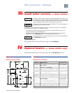
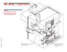
Wiring procedure
1. Mount all controls as directed in Section III of this
Supplement. Refer to the assembly illustration for
the type of boiler installed (Figure 6, 8 or 10).
2. Mount the junction box supplied with the boiler on
the inside left (or right) side of the jacket as shown
in the assembly illustration (using screws and nuts
provided). Mount the junction box on the same
end of the boiler as the controls will be
mounted
.
3. Attach the transformer/relay to the junction box.
4. Mount the CSD-1 control panel on the jacket
interior panel as shown in the appropriate
assembly illustration (Figure 6, 8 or 10), using
screws and nuts provided.
5. Crimp connect ¹⁄₄" spade terminals (provided) to
the pilot gas valve wires if not already done in
Section I of this Supplement.
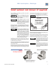
6. If optional vent damper is installed, make sure
damper harness has been routed through a strain
relief bushing in the jacket and damper actuator as
directed in Section I of this Supplement. Secure
damper harness conduit to top of jacket with
clamps provided.
7. The main gas valve wires are pre-attached to the
CSD-1 control panel. The spark and sense wires
from the pilot are factory installed to the pilot.
Connect these wires as shown in the wiring
diagram.
8. Use the wiring harness provided with the boiler to
complete wiring of the remaining components
according to the appropriate wiring diagram and
assembly illustration.
Support gas line securely. Do not
support weight of gas line off of boiler
gas train.
Purge air from gas piping and perform gas line and gas
connection leak test per Section V of the EGH Manual.