


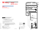
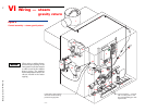
EGH-105 to EGH-125 EGH-105 to EGH-125
EGH-105 to EGH-125 EGH-105 to EGH-125
EGH-105 to EGH-125 Control Supplement
Part Number 550-110-677/0299
6
Piping connectionsII
Connect steam (water) piping to the boiler per EGH Manual Section II.
Water boilers — make provision for mounting probe low water cutoff in the supply or return
piping, above the top of the boiler. The low water cutoff must be between the boiler and any
isolation valve(s).
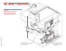
Install boiler controls — water boilersIII
The controls may be mounted on either end of the boiler. Mount all controls
on the same end. The junction box (electrical entrance) must also be mounted
on the same end as the controls.
Install the probe low water cutoff in the supply or return piping, above the
top of the boiler. The low water cutoff must be mounted between the boiler
and any isolation valve(s) installed in the piping.
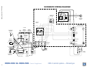
Install water trim components as required by ASME CSD-1, latest edition. See Figure 3 and
Table 2 for controls required and tapping usage. See Figure 6 for finished assembly.
Plug all unused tappings.
All piping and control connections must also comply with the EGH Manual.
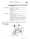
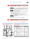
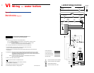
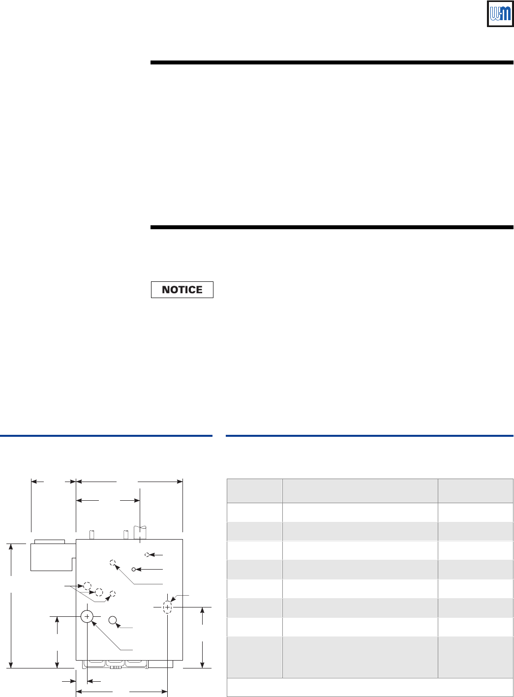
Figure 3
Water boiler connections
Table 2
Water boiler connections
32¾"
13½"
11¾" 27 / "
5
8
16 / "
3
16
2/"
11
16
16/"
5
8
24"
EG
D
Return
Not
used
Supply
H
S
V
L
677-08
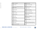
Tapping Application W-M Part No.
D Boiler drain connection —
E ASME relief valve (per EGH manual) —
G Pipe to air vent or compression tank —
H Honeywell L4006E-1000 M/R limit 510-312-041
L Pressure/temperature gauge 510-218-097
S Temperature limit control, auto reset 510-312-209
V Gas supply connection (right or left) —
Not shown
McDonnell & Miller PS852M-24 M/R
probe LWCO (Mount in supply or
return piping, above top of boiler)
511-114-530
Plug all tappings not used.