


General wiring requirements:
Electric shock hazard. Can cause
severe personal injury or death if
power source, including service switch on boiler, is
not disconnected before installing or servicing.
• Installations must follow these codes:
—
National Electrical Code, ANSI/NFPA 70,
latest edition and any additional national,
state or local codes.
— In Canada, CSA C22.1 Canadian Electrical
Code Part One and any local codes.
• Wiring must be N.E.C. Class 1. If original wire
as supplied with boiler must be replaced, type
105°C wire or equivalent must be used. Supply
wiring to boiler and additional control wiring
must be 14 ga. or heavier.
• Provide electrical ground at boiler as required
by codes.
Thermostat wiring:
• Install thermostat on inside wall away from
influences of drafts, hot or cold water pipes,
lighting fixtures, television, sun rays or
fireplaces.
• Follow instructions with thermostat. If it has a
heat anticipator, set heat anticipator in
thermostat to match power requirements of
equipment connected to it. Boiler wiring
diagrams give setting for standard equipment.
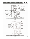
Junction box (furnished):
• Junction box houses electrical connections for
all boiler components.
• “P” boilers have harnesses furnished.
• “A” boilers are furnished with burner and limit
harnesses.
• All field-provided high voltage wiring must be
sheathed in flexible metal conduit.
• Connect incoming line voltage “HOT” wire to
service switch, and neutral wire to white wire.
Field-install equipment ground wire to green
wire with wire nut.
• Service switch (15 amp) is provided with boiler.
“A” boilers — install switch as shown.
• Some local codes may require an emergency
shut-off switch installed at a location away
from boiler. Follow local codes.
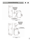
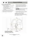
Burner wiring:
• Burner harness incorporates a disconnect
plug, providing a convenient way to disconnect
wiring when burner mounting door is opened.
• All “P” boilers have a power disconnect plug
installed on burner.
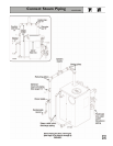
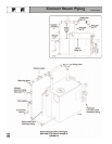
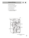
• On “A” boilers, mount the plug (provided in
steam trim carton) on the burner housing as
shown in FIGURE 13 or 14. For Carlin
burners, screw burner plug into threaded
conduit coupling, then mount this assembly to
the burner housing using the chase nipple.
Route wires through housing and make
connections in burner junction box as shown
in boiler wiring diagram.
19
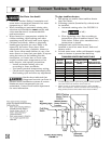
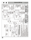
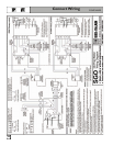
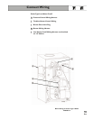
Connect Wiring
To wire boilers, refer to the following pages:
Pages 20 to 21 Float-Type LWCO
Pages 22 to 23 Probe-Type LWCO