


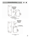
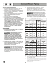
General piping information:
• Hartford Loop piping arrangement and wet
return are required for steam boilers.
• Maintain 24-inch minimum from waterline to
bottom of header (minimum 50
7
/8" from floor
or top of foundation).
• When using condensate receiver, feed pump
must be energized by boiler-mounted
pump control.
• Use swing joints in steam piping.
• If installation is to comply with ASME or
Canadian requirements, an additional pressure
limit control is needed. Install control between
existing pressure control and pressure gauge.
Control must be installed with siphon
(supplied with boiler) between control and
boiler. Set control to minimum of 5 psi above
setpoint of existing control and maximum
setting of 15 psi. Wire as shown on boiler
wiring diagram.
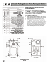
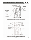
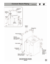
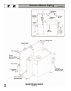
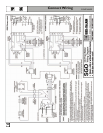
Install piping:
1. See Tables at right and FIGURE 9 on page 15
or FIGURE 10 on page 16.
Improperly piped systems or
undersized piping can
contribute to erratic boiler operation and
possible boiler or system damage. Piping
system must be installed as shown, using
minimum pipe sizes shown. Consult your
Weil-McLain distributor or sales office before
installing alternate piping.
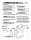
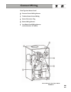
2. Install relief valve vertically in “R” tapping on
back of boiler. See FIGURE 9 or 10 and also
refer to tag attached to relief valve for
manufacturer’s instructions.
Pipe relief valve discharge line
near floor close to floor drain to
eliminate potential of severe burns. Do not
pipe to any area where freezing could occur.
Do not plug, valve or place any obstruction in
discharge line.
3. Float-type low water cutoff only — install
blowdown line in bottom of cutoff. See
FIGURE 9 or 10 and also refer to low water
cutoff manufacturer’s instructions for details.
Pipe blowdown line near floor
close to floor drain to eliminate
potential of severe burns. Do not pipe to any
area where freezing could occur. Do not plug,
valve or place any obstruction in discharge line.
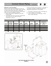
* Based on ASHRAE Fundamentals Handbook recommendations, allowing
½ oz. pressure drop at 0 psig.
** Based on ASHRAE Fundamentals Handbook recommendations, allowing
2 oz. pressure drop per 100 feet of pipe at 3.5 psig. Maintain minimum
24" height from waterline to bottom of header.
Can be reduced to 2".
14
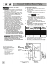
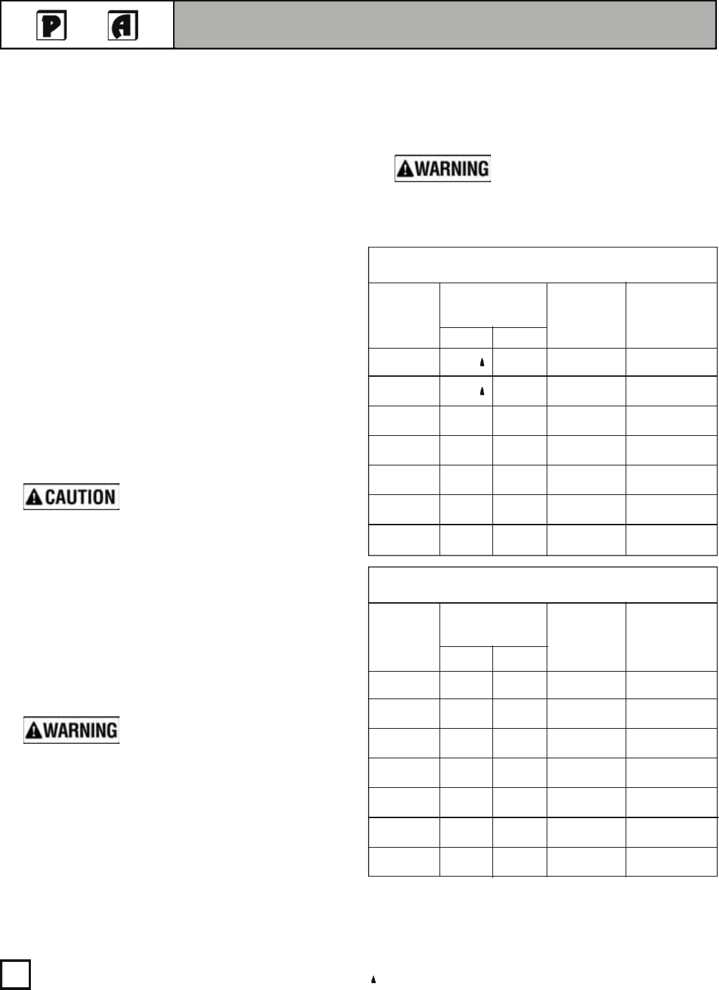
Connect Steam Piping
STEAM PIPING SIZE TABLE
FOR ONE AND TWO-PIPE SYSTEMS
SGO-3 2½" — 2½" 1½"
SGO-4 2½" — 2½" 1½"
SGO-5 2½" — 3" 1½"
SGO-6 2½" 2½" 3" 1½"
SGO-7 2½" 2½" 3" 1½"
SGO-8 2½" 2½" 3" 1½"
SGO-9 2½" 2½" 3" 1½"
BOILER
MODEL
NUMBER
HEADER
PIPE
SIZE
“H” * *
RISER
PIPE SIZE *
AB
EQUALIZER
PIPE SIZE
“J”
STEAM PIPING SIZE TABLE
FOR ONE-PIPE COUNTERFLOW SYSTEMS
SGO-3 2½" — 2½" 1½"
SGO-4 2½" — 2½" 1½"
SGO-5 2½" — 3" 1½"
SGO-6 2½" 2½" 4" 1½"
SGO-7 2½" 2½" 4" 1½"
SGO-8 2½" 2½" 4" 1½"
SGO-9 2½" 2½" 4" 1½"
BOILER
MODEL
NUMBER
HEADER
PIPE
SIZE
“H” * *
RISER
PIPE SIZE *
AB
EQUALIZER
PIPE SIZE
“J”