


Part number 550-141-396/0801
4
PER Series 3 Electric-Hydronic Boilers Installation Instructions
Piping the boiler
After the boiler is secured to the wall, attach the supply
and return piping. Refer to Table 2 for minimum pipe
sizes.
Install manual shut-off valves in the supply and return
lines to facilitate servicing the boiler. Model PER boilers
are provided with a built-in air elimination system using
a float-type automatic air vent. Refer to the boiler line
drawings and proceed as follows:
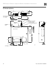
1. Install the pressure-temperature gauge and ¾"-¼"
bushing in the 1¼" x 1¼" x ¾" tee installed on the
boiler supply connection. See “Dimensions” on
page 12.
2. The ¾" tapping, located to the left of the supply
tapping, must be used for either an automatic
venting device or piped directly to a standard closed
expansion tank.
3. Install the pressure relief valve in the ¾" tapping
located on the top left hand side of the boiler (see
“Dimensions” on page 12). Pipe the relief valve
outlet to a floor drain or near the floor. Do not pipe
the relief valve to any area where freezing
temperatures might be encountered.
Pipe relief valve discharge line near
floor close to floor drain to eliminate
potential of severe burns. Do not
pipe to any area where freezing
could occur. Do not plug valve or
place any obstruction in discharge
line.
4. Connect the system supply piping to the tapping
located at the right on the top of the boiler casting.
5. Connect the system return piping to the circulator
flange. When solder fittings are used, be sure that
the gasket is not between the flanges when the solder
connection is made.
6. A Fill-Trol system is supplied with PER boilers
follow the instructions attached to the valve.
Pre-installation continued
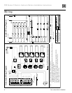
Wiring the boiler
Electric shock hazard. Can cause
severe personal injury or death if
power source, including service
switch on boiler, is not disconnected
before installing or servicing.
The Model PER electric-hydronic boilers are pre-wired
for use with 240-volt, single phase, 50/60-hertz power.
Refer to Figure 1 on page 13 for the reduction in boiler
capacity when the line voltage is less than 240 volts.
An opening is provided in the left side of the jacket top
panel for the field wiring. Refer to Dimensions, page
12, and Ratings, page 13, for recommended wire sizes.
All wiring must conform to the requirements of the
National Electrical Code and any additional National,
State or Local Code Requirements having jurisdiction.
All safety circuit wiring should be N.E.C. Class 1. Do
not use aluminum wire.
When a PER boiler is used in a zoned system, the zone
valves must be powered from an independent source,
and have electrically isolated end switches or isolating
relays wired in parallel to the boiler thermostat
terminals.
Do not attempt to power zone valves
from the transformer in the boiler
control system.
Control system
The control system for the PER electric boiler has
electronic and thermal time delays, which are employed
to sequence elements on and to sequence elements off
in reverse order. The contactors used in the system
disconnect all current from the heating elements.
The circulator control utilizes a single pole relay.
Low and high limit functions are combined in a dual
limit control. The control system is operated from a
low voltage transformer.
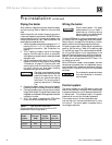
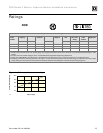
Table 2 Pipe sizes and flow rates
(Recommended minimum pipe size with 20°F
temperature rise through boiler.)
Boiler
model
number
Maximum
flow rate
GPM
Minimum
supply
pipe size
Minimum
return
pipe size
PER-15 5.20 ¾" ¾"
PER-20 6.90 1" 1"
PER-25 8.60 1¼" 1¼"