


Part number 550-141-396/0801
3
PER Series 3 Electric-Hydronic Boilers Installation Instructions
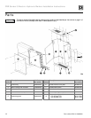
Mounting the boiler
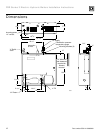
Normally, the boiler will be installed against a frame or
masonry wall. If the wall surface is rough or uneven, it
may be necessary to mount plywood on the wall, then
mount the boiler on the plywood. Refer to
“Dimensions” on page 12 and “Ratings” on page 13, and
note the boiler weight. Be sure that the wall structure
will support the boiler and its piping.
The
9
/
16
" top mounting holes and
5
/
16
" lower mounting
holes are on 16-inch centers to permit installation on
studs in standard wall construction. The use of ¼" x
2½" lag screws is recommended for mounting the boiler.
The head diameters of the top two screws must not
exceed
9
/
16
".
1. Locate the top mounting holes so that the boiler
will be level. Install the screws so that the heads
protrude ¾" from the wall.
2. Raise the boiler to mounting position by placing a
board across the bottom of the boiler or by grasping
the lower left and right inside corners. Do not
attempt to lift the boiler by grasping the bottom
jacket cross tie.
3. Place the top brackets over the lag screws and then
install screws through the lower mounting holes.
The top screws can now be tightened.
Locating the boiler
The compact construction of the electric-hydronic
boiler permits installation in an alcove, storeroom or
other small area. The location chosen should have
convenient electrical service.
Allow sufficient clearance above and below the boiler
cabinet to permit installation of supply and return
piping. A minimum of 6 inches is required at the top of
the boiler for installation and accessories. A clearance
of 10 inches is required on the right hand side for
removal of the elements.
General instructions
The Weil-McLain Model PER electric-hydronic boilers
are assembled units designed for use in forced hot water
heating systems. The suggested design temperature rise
through the boiler is 20°F. The PER boiler is a complete
package including the circulator and expansion tank.
Low flow rates through the boiler at elevated
temperatures should be avoided. The structure to be
heated should be insulated in the conventional manner
used in your area for electrically heated buildings. Boiler
must be installed in accordance with these instructions
so as not to void our warranty.
Open the boiler crate and check the contents. In the
event of shortage or damage, notify the transportation
company immediately.
Expansion tank sizing
Undersized expansion tanks cause system water to be
lost from relief valve and makeup water added through
fill valve. Eventual section failure can result.
If a Fill-Trol system is used, refer to Table 1 for proper sizing. If Fill-Trol
action is not desired, size the expansion tank according to the water volume
of the system. If a standard closed expansion tank (without a diaphragm)
is used, the air vent tapping on the boiler casting makes a convenient point
of connection. The No. 109 Fill-Trol is furnished as standard equipment.
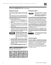
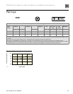
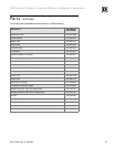
Table 1 Expansion tank sizing (Tank sizing based on 200 °F
average system temperature.)
Hydrostatic pressure test
Pressure test boiler before attaching piping or electrical supply.
1. Install air vent in tapping on top of boiler.
2. Plug remaining tappings, including relief valve opening.
3. Connect water supply. Fill boiler and purge all air. For more than 10
minutes, pressure-test at 1½ times maximum working pressure.
Do not leave boiler unattended. Cold water fill could
expand and cause excess pressure, resulting in severe
personal injury, death or substantial property damage.
4. Check for maintained gauge pressure. Visually check for leaks if gauge
pressure drops.
5. Drain boiler and repair leaks if found.
Leaks must be repaired at once. Failure to do so can
damage boiler, resulting in substantial property damage.
6. Retest boiler after repairing leaks.
7. Remove testing plugs and air vent.
Do not use petroleum-based cleaning or sealing
compounds in boiler system. Severe damage to boiler
will result, causing substantial property damage.
Pre-installation
Boiler
model
number
Standard Fill-Trol tank
(for series loop or one-pipe system
with convector baseboard)
Additional Ex-Trol tank
(for cast-iron radiators or
cast-iron baseboard)
PER-15 No. 109 No. 15
PER-20 No. 109 No. 15
PER-25 No. 109 No. 15
Note: Gravity systems converted to a forced hot water system usually require
additional compression tank capacity.