


Tools Needed:
24
Tools Needed:
Please Do Not Return This Product To The Store. Contact your local Wayne-Dalton dealer.
To find your Wayne-Dalton dealer; refer to your local yellow pages / business listings or go to Find a dealer area online at www.wayne-dalton.com
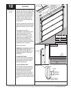
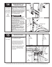
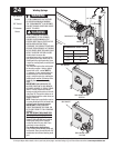
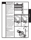
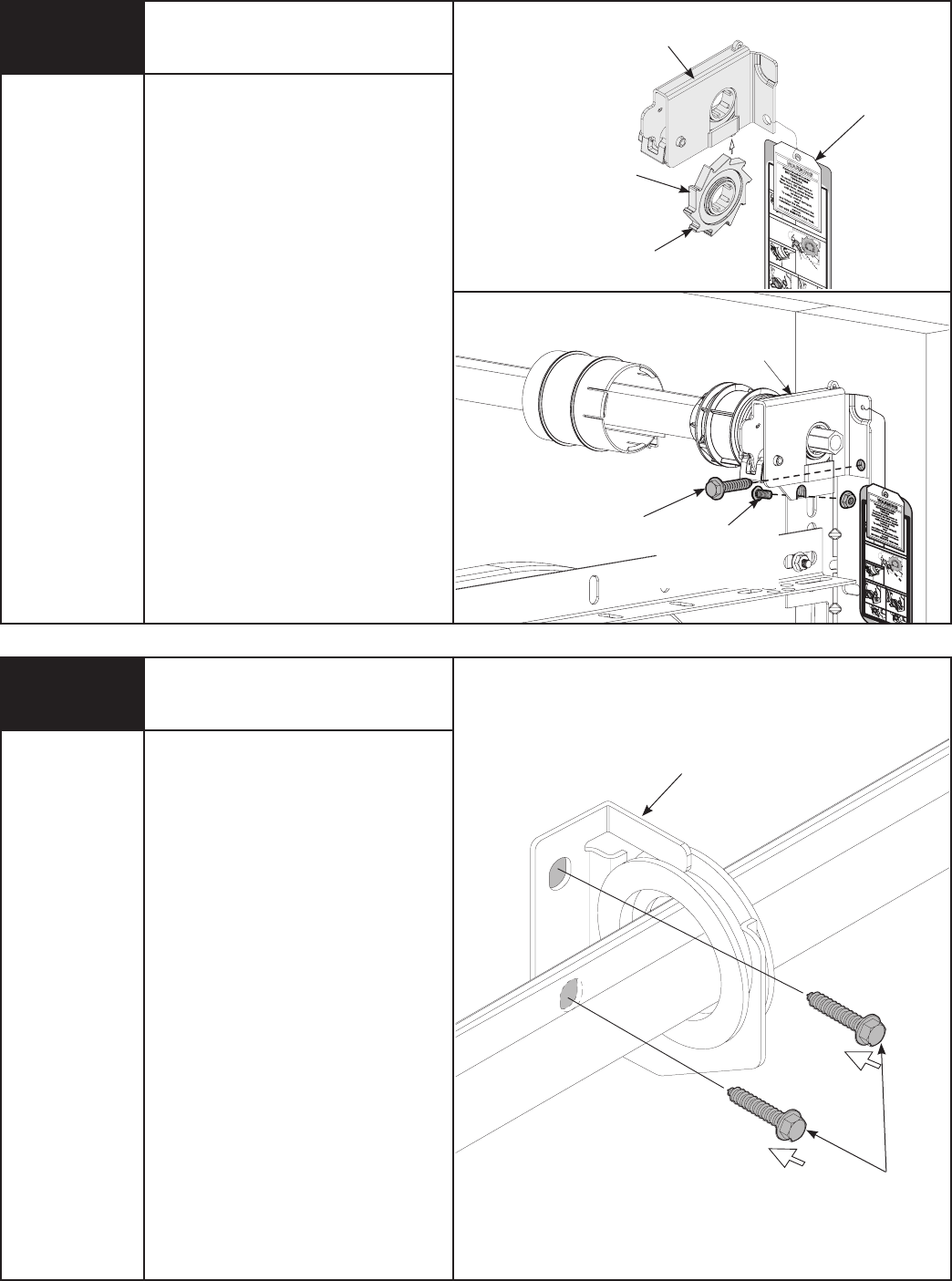
End Brackets Continued...
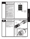
Cable Drum
No space between Ratchet
Pawl and Cable Drum
indicates engagement
Cable Drum
Ratchet Pawl
ENGAGED SIDE VIEW
No space between
Ratchet Pawl and
Cable Drum
ENGAGED UNDERNEATH VIEW
Space between Ratchet Pawl
and Cable Drum
non-indicates engagement
Cable Drum
Ratchet Pawl
DISENGAGED SIDE VIEW
No space between
Ratchet Pawl and
DISENGAGED U
NDERNEATH VIEW
UPPER POSITION
LOWER POSITION
LOWER POSITION SIDE VIEW
UPPER POSITION SIDE VIEW
Ratchet Pawl in Lower Position
Ratchet Pawl in Upper Position
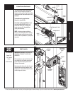
Use these Illustration, in conjunction with the Instructions on the other side of
this label.
W A RNING
Rachet Bracket is under
EXTREME SPRING
TENSION
.
To avoid possible severe or
fatal injury,
DO NOT
remove
fasteners from ratchet bracket
until spring(s) are fully
wnwound.
To safely unwind spring(s)
read
and follow the directions in the
installation instructions/owners
manual.
DO NOT REMOVE THIS TAG.
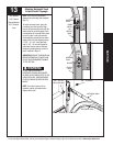
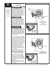
RIGHT END
BRACKET
RATCHET
WHEEL
TEETH POINTING
UPWARD
Cab
le Drum
No s
pace betwe
en Ratchet
Pawl and C
able Dr
um
indicates engagem
ent
Cable Drum
Ratchet Paw
l
ENG
AGED
SIDE VIEW
No s
pace
between
Rat
chet Pawl
and
Cable Drum
ENGAGED UNDERNEA
TH V
IEW
Space b
etween Ratche
t Pawl
and Cab
le D
rum
non-indicates engagem
ent
Cab
le Drum
Ratchet Paw
l
DISENGA
GED
SIDE VIEW
No s
pace between
Ratchet
Pawl and
DISENGA
GED U
NDERNEAT
H VIEW
UPPER
POSI
TION
LOW
ER POSITION
LOW
ER POSITION
SIDE VIEW
UPPER POSI
TION
SIDE VIEW
Ratchet Paw
l in Lower
Position
Ratchet Pawl
in U
pper Po
sition
Use t
hese I
llus
tration, i
n conjunction with the Instructions on the other side of
this label.
WARNING
Rachet Bracket is under
EXTREME SPRING
TENSION
.
To avoid possible severe or
fatal injury,
DO NOT
remove
fasteners from ratchet bracket
until spring(s) are fully
wnwo
und.
To
safely unwind spring(s)
read
and follow the directions in the
installation instructions/owners
manual.
DO NOT REMOVE THIS TAG.
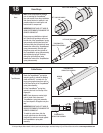
5/16” X 1-5/8”
HEX HEAD LAG
5/16” - 18 x 3/4”
CARRIAGE BOLT
AND HEX NUT
RIGHT END
BRACKET
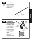
WARNING TAG
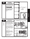
21
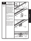
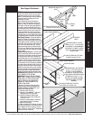
CENTER
BRACKET
BUSHING
ASSEMBLY
(2) 5/16” X 1-5/8”
HEX HEAD LAG
SCREWS
NOTE: If you are installing the idrive
®
opener with your garage door, skip this
step.
NOTE: If you are not installing the
idrive
®
opener on your garage door, you
must install the center bracket bushing
assembly. Follow these instructions for
non-idrive
®
operated garage doors.
To locate the center bracket, mark the
header halfway between the flagangles
and level the TorqueMaster
®
spring tube.
Drill 3/16” pilot holes into header for the
lag screws. Fasten the metal bracket to
the header using (2) 5/16” X 1-5/8” lag
screws.
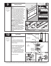
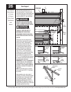
Securing Center Bracket
Assembly
Power Drill
3/16” Drill Bit
7/16” Socket
Driver
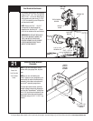
First secure end bracket to the flagangle
using (1) 5/16” - 18 x 3/4” carriage bolt
and (1) 5/16” - 18 hex nut. Now, secure
end bracket to the jamb using (1) 5/16”
x 1-5/8” hex head lag screw. Repeat for
left hand end bracket.
NOTE: Ensure the 5/16” - 18 x 3/4”
carriage bolt is going through the
flagangle first, and the 5/16” - 18 hex
nut is on the outside of the end bracket.
IMPORTANT: IF RATCHET GEAR SLIPS
OUT OF END BRACKET, ENSURE THE
TEETH ON RATCHET WHEEL ARE
POINTING UPWARD IN A CLOCKWISE
POSITION WHEN SLIDING IT BACK
INSIDE THE END BRACKET.