


17
Please Do Not Return This Product To The Store. Contact your local Wayne-Dalton dealer. To find your local Wayne-Dalton dealer, refer to your
local yellow pages/business listings or go to the Find a Dealer section online at www.wayne-dalton.com
Tools Needed:
Tools Needed:
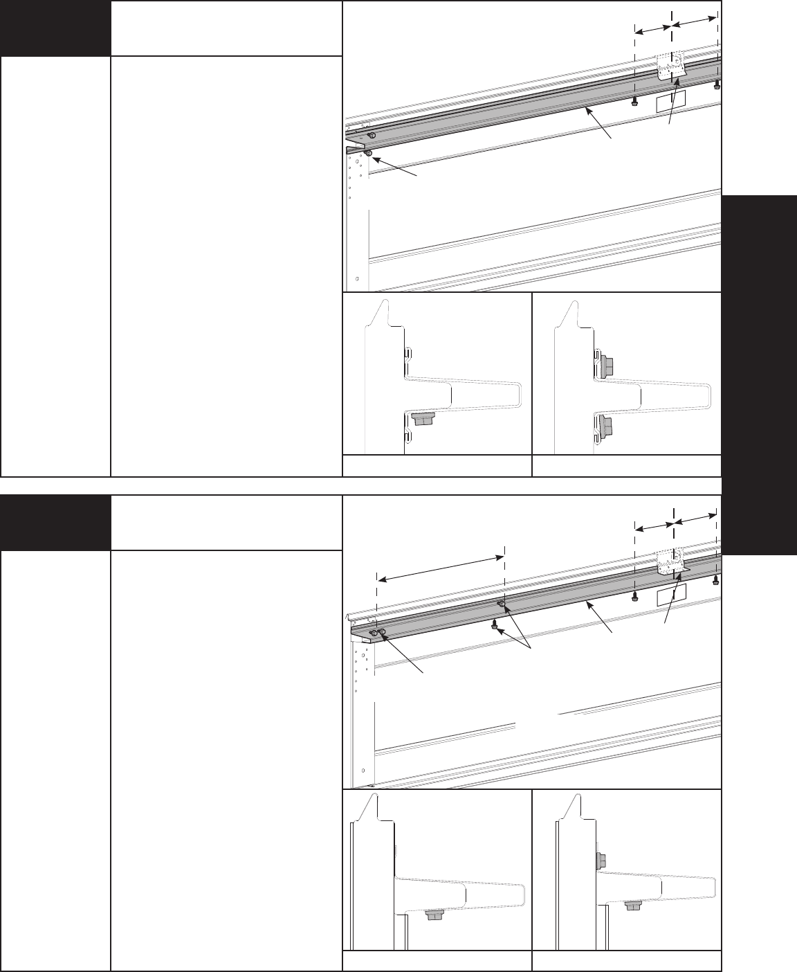
INSTALLATION
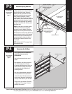
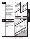
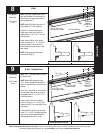
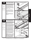
NOTE: If you have a model 9600 Series
door with windows in the top section or
9100 Sonoma (8’ high), skip this step
and complete step 9.
NOTE: Model 9100 Series door over 13’
wide require a 3” U-Bar (supplied).
Place the 3” u-bar over the top rib.
Fasten each end of the u-bar to the
endstile with (2) 1/4”- 20 x 11/16” self
drilling screws.
Fasten center of the u-bar as shown
to the rib using (2) 1/4”- 14 x 5/8” self
tapping screws 6” to the left and 6”
inches to the right of the center of the
door section.
NOTE: Upon completion of this step,
continue with Step 10.
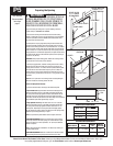
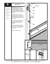
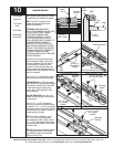
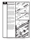
NOTE: If a 3” U-Bar was installed in step
8, skip this step.
NOTE: Model 9600 glazed top doors
13’-0” wide or greater will be supplied
with a 3” asymmetrical u-bar for the top
section.
Place the 3” asymmetrical u-bar over the
top rib. Fasten each end of the u-bar to
the endstile with (2) 1/4”- 20 x 11/16”
self drilling screws.
Fasten center of the u-bar as shown
to the rib using (2) 1/4”- 14 x 5/8” self
tapping screws 6” off of the center of the
door section.
Fasten both walls of the u-bar as shown
using 1/4”- 14 x 5/8” self tapping screws
every 30-36 inches. (approximately 18
self tapping screws per 18’ u-bar)
U-Bar
U-Bar - Asymmetrical
(4) 1/4”- 20 X 11/16”
SELF DRILLING SCREWS
Power Drill
7/16” Socket
Driver
Power Drill
7/16” Socket
Driver
8
9
U-BAR
OPERATOR
BRACKET
(INSTALLED IN
STEP 10)
TOP DOOR SECTION
6”
6”
ATTACHING CENTER OF U-BAR ATTACHING ENDS OF U-BAR
(2) 1/4”- 20 X 11/16”
SELF DRILLING SCREWS
1/4”- 14 X 5/8” SELF
TAPPING SCREWS
U-BAR
OPERATOR
BRACKET
(INSTALLED IN
STEP 10)
TOP DOOR SECTION
30” TO 36”
6”
6”
ATTACHING CENTER OF U-BAR
ATTACHING INTERMEDIATES OF U-BAR