


14
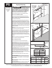
Please Do Not Return This Product To The Store. Contact your local Wayne-Dalton dealer. To find your local Wayne-Dalton dealer, refer to your
local yellow pages/business listings or go to the Find a Dealer section online at www.wayne-dalton.com
Tools Needed:
5
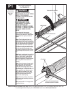
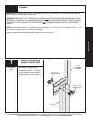
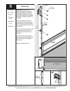
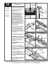
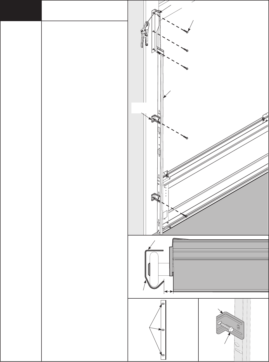
Vertical Track
IMPORTANT: THE TOPS OF THE
VERTICAL TRACKS MUST BE LEVEL
FROM SIDE TO SIDE. IF THE BOTTOM
SECTION WAS SHIMMED TO LEVEL IT.
THE VERTICAL TRACK ON THE SHIMMED
SIDE, MUST BE RAISED THE HEIGHT OF
THE SHIM.
Position the left hand vertical track
assembly over the rollers of the bottom
section. Make sure the counterbalance
cable is located between the rollers and
the door jamb.
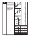
Drill 3/16” pilot holes for the lag screws.
Loosely fasten jamb brackets and
flagangle to the jamb using 5/16” x 2”
lag screws.
On the bottom jamb bracket, tighten
the lag screw securing the bottom jamb
bracket to the jamb, to maintain the
5/8” spacing.
Repeat for the right hand side.
BOTTOM
SECTION
BOTTOM SECTION
VERTICAL TRACK
ROLLER
5/16” X 2”
LAG SCREWS
FLAGANGLE
VERTICAL
TRACK
ASSEMBLY
JAMB
BRACKET
3/16” Drill Bit
Power Drill
7/16” Socket
Driver
Tape Measure
Level
(2) Vice Grips
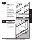
5/8”
LAG
SCREW
LOCATIONS
LAG
SCREW
JAMB
BRACKET