


NOTE: When attaching operator bracket to top section with u-bar, apply additional pressure to
thread into the u-bar.
(2) #12 x 1/2”
Phillips head screws
(5) 1/4”- 14 x 5/8”
Self-tapping screws
Top Section
Tools: Hammer, Step ladder, Tape measure
14
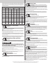
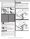
Place the top section in the opening. Temporarily secure the top section by driving a nail in the
header near the center of the door and bending it over the top section. Now, flip up the hinge
leaves, hold tight against section, and fasten center hinges first and end hinges last (refer
to step, Stacking Sections). Vertical track alignment is critical. Position flag angle between
1-11/16” (43 mm) to 1-3/4” (44 mm) from the edge of the door; tighten the bottom lag screw.
Flag angles must be parallel to the door sections. Repeat for other side.
IMPORTANT: THE DIMENSION BETWEEN THE FLAG ANGLES MUST BE DOOR WIDTH PLUS
3-3/8” (86MM) TO 3-1/2” (89 MM) FOR SMOOTH, SAFE DOOR OPERATION.
For Q.I. track:
Complete the vertical track installation by securing the jamb bracket(s) and tightening the other
lag screws. Repeat for other side.
For F.A. track:
Complete the vertical track installation by securing the jamb bracket(s) and tightening the other
lag screws. Push the vertical track against the rollers so that the rollers are touching the deepest
part of the curved side of the track; tighten all the track bolts and nuts. Repeat for other side.
Attach Horizontal Tracks to Q.I. Flag Angles
Tools: Ratchet wrench, 9/16” Socket, 9/16” Wrench, level, Step ladder
15
NOTE: If you have Q.I. flag angles, complete this step.
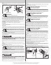
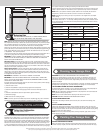
To install horizontal track, place the curved end over the top roller of the top section. Align key
slot of the horizontal track with the Q.I. tab of the flag angle. Push curved portion of horizontal
track down to lock in place.
WARNING WARNING
DO NOT RAISE DOOR UNTIL HORIZONTAL TRACKS ARE SECURED AT REAR, AS
OUTLINED IN STEP, REAR SUPPORT, OR DOOR COULD FALL FROM OVERHEAD
POSITION CAUSING SEVERE OR FATAL INJURY.
Level the horizontal track assembly and bolt the horizontal angle to the first encountered slot in
the flag angle using (1) 3/8”-16 x 3/4” truss head bolt and (1) 3/8”-16 hex nut. Repeat for other
side.
Remove the nail that was temporarily holding the top section in place, installed in step, Top
Section.
IMPORTANT: FAILURE TO REMOVE NAIL BEFORE ATTEMPTING TO RAISE DOOR COULD CAUSE
PERMANENT DAMAGE TO TOP SECTION.
NOTE: If an idrive
®
opener will be installed, position horizontal tracks slightly above level.
Attach Horizontal Tracks to F.A. Flag Angles
Tools: Ratchet wrench, 7/16” Socket, 9/16” Socket, 9/16” Wrench,
level, Step ladder
16
NOTE: If you have F.A. flag angles, complete this step.
To install horizontal track, place the curved end over the top roller of the top section. Align the
bottom of the horizontal track with the top of the vertical track. If you have Q.I. horizontal track,
tighten the horizontal track to the flag angle with a stud plate and (2) 1/4”-20 flange hex nuts. If
you have universal horizontal track, tighten the horizontal track to the flag angle with (2) 1/4”-20
x 9/16” track bolts and (2) 1/4”-20 flange hex nuts.
WARNING WARNING
DO NOT RAISE DOOR UNTIL HORIZONTAL TRACKS ARE SECURED AT REAR, AS
OUTLINED IN STEP, REAR SUPPORT, OR DOOR COULD FALL FROM OVERHEAD
POSITION CAUSING SEVERE OR FATAL INJURY.
Level the horizontal track assembly and bolt the horizontal angle to the first encountered slot in
the flag angle using (1) 3/8”-16 x 3/4” truss head bolt and (1) 3/8”-16 hex nut. Repeat for other
side.
Remove the nail that was temporarily holding the top section in place, installed in step, Top
Section.
IMPORTANT: FAILURE TO REMOVE NAIL BEFORE ATTEMPTING TO RAISE DOOR COULD CAUSE
PERMANENT DAMAGE TO TOP SECTION.
NOTE: If an idrive
®
opener will be installed, position horizontal tracks slightly above level.
Adjusting Top Brackets
Tools: 7/16” Wrench, Step ladder
17
With horizontal tracks installed, you can now adjust the top brackets. Vertically align the top sec-
tion of the door with the lower sections. Once aligned, position the top bracket slide, out against
the horizontal track. Maintaining the slide’s position, tighten the (2) 1/4”-20 flange hex nuts to
secure the top bracket slide to the top bracket base. Repeat for other side.
TorqueMaster
®
Spring Tube
Tools: None
18
TorqueMaster
®
springs come lubricated and pre-assembled inside the TorqueMaster
®
spring
tube. To prepare for install, lay the TorqueMaster
®
spring tube assembly on the floor, inside
garage, in front of the door, and with the labeled end to the left.
Center Bearing Bracket
Tools: None
19
NOTE: If you are installing the idrive
®
opener with your garage door, skip this step and go to
your idrive
®
Installation Instructions and Owner’s Manual. After completing the steps up to and
including, Drum Wrap Installation of your idrive
®
Installation Instructions and Owner’s Manual
continue with Step, Rear Support, of this door Installation Instructions and Owner’s Manual.
NOTE: If you are not installing the idrive
®
opener on your garage door, you must install the cen-
ter bearing bracket assembly. Follow these instructions for non-idrive
®
operated garage doors.
Being cam shaped, the center bearing bracket assembly only fits one way. Slide the center bear-
ing bracket assembly towards the center of the TorqueMaster
®
spring tube, from the right side.
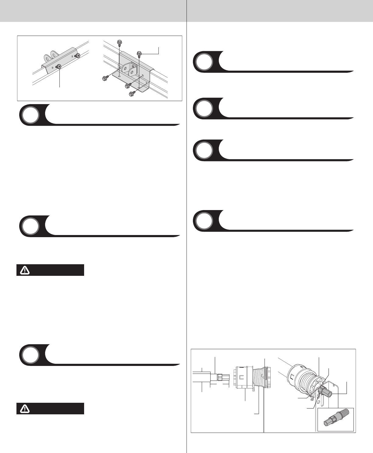
Cable Drum Assemblies
Tools: Tape measure, Step ladder
20
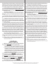
Shake the TorqueMaster
®
spring tube assembly gently to extend the winding shafts out about 5”
on each side. For single spring applications, there will be no left hand spring in the TorqueMas-
ter
®
spring tube assembly. Lift the TorqueMaster
®
spring tube assembly and rest it on top of the
flag angles.
NOTE: Cable drum assemblies are marked right and left hand and consist of a cable drum
and drum wrap. Cable drums and TorqueMaster
®
spring tube assembly are cam shaped to fit
together only one way.
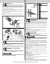
Starting on the right hand side, slide the drum wrap over to access the counterbalance cable.
Pre-wrap the cable drum with the counterbalance cable 1-1/2 wraps as shown.
Position the TorqueMaster
®
spring tube assembly so the can peak is pointing straight up. Slide
the cable drum over the winding shaft until the cable drum seats against the TorqueMaster
®
spring tube assembly.
The winding shaft must extend past the cable drum far enough to expose the splines and the
grooves. Align the winding shaft grooves with the round notch in the flag angle.
For double spring applications: Repeat for left hand side.
For single spring applications: Pre-wrap the left hand cable drum with counterbalance cable
1-1/2 wraps and insert the loose winding shaft into the cable drum prior to sliding the cable
drum over the TorqueMaster
®
spring tube assembly.
NOTE: On single spring applications, take care in handling the loose winding shaft (left side) so
that it does not slide back into the TorqueMaster
®
spring tube assembly.
Torquemaster
®
spring
tube assembly
Cam peak
straight
Winding shaft
Counterbalance cable
1-1/2 wraps
Drum wrap
Grooves
Cable drum
Splines
Round notch
Winding
shaft
Right cable
drum
5”
Loose winding shaft
4
Please Do Not Return This Product To The Store. Contact your local Wayne-Dalton dealer. To find your local Wayne-Dalton dealer,
refer to your local yellow pages business listings or go to the Find a Dealer section online at www.wayne-dalton.com