


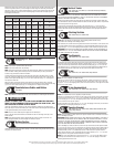
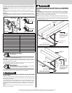

Measure the length of the vertical tracks. Using the jamb bracket schedule, determine the place-
ment of the jamb brackets for your door height and track length. To install the jamb brackets,
align the Q.I. tab on the Q.I. jamb bracket with the Q.I. feature in the vertical track and turn the
bracket perpendicular to the track so the mounting flange is toward the back (flat) leg of the
track. Repeat for other side.
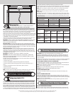
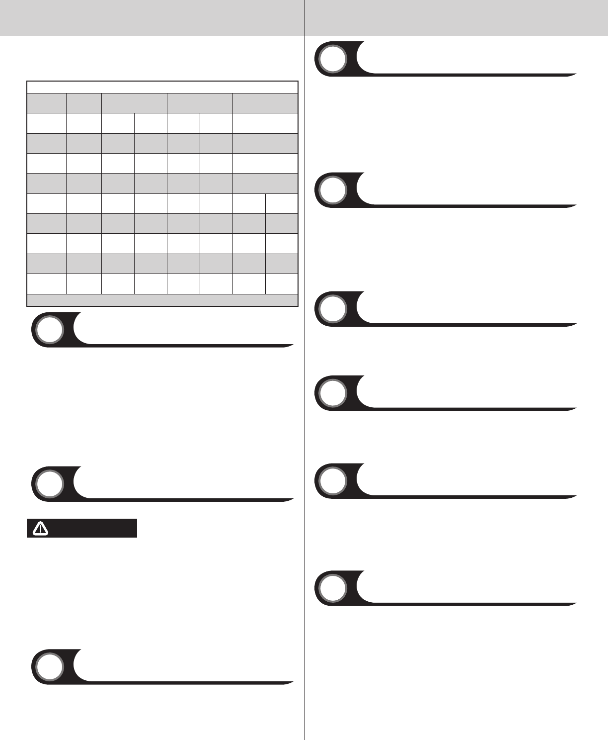
JAMB BRACKET SCHEDULE
DOOR HEIGHT
TRACK
LENGTH
1ST SET 2ND SET 3RD SET
6’0”
64” (1626
mm)
5 M 6 B NA
6’5”
69” (1753
mm)
3 B 6 M NA
6’8”
72” (1829
mm)
3 B 6 M NA
7’0”
76” (1930
mm)
3 B 7 T NA
7’3”
79”
(2007mm)
3 B 5 B 6 B
7’6”
82” (2083
mm)
3 B 5 B 6 B
7’9”
85” (2159
mm)
3 B 5 B 6 B
8’0” 4-SEC
88”
(2235mm)
3 M 6 T 7 M
8’0” 5-SEC
88” (2235
mm)
3 B 7 T 8 T
B= BOTTOM HOLE, M= MIDDLE HOLE, T= TOP HOLE
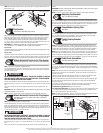
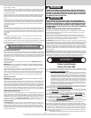
Attaching F.A. Jamb Brackets
Tools: None
5
NOTE: If you have Q.I. jamb brackets, skip this step.
NOTE: If you have riveted track, skip this step.
NOTE: The bottom jamb bracket is always the shortest bracket, while the center jamb bracket
is the next tallest. If three jamb brackets per side are included with your door, you will have
received a top jamb bracket, which is the tallest.
To attach the bottom jamb bracket, locate lower hole of the hole/ slot pattern of the 1st hole
set on the vertical track. Align the slot in the jamb bracket with the lower hole of the hole/ slot
pattern. Secure jamb bracket using (1) 1/4”-20 x 9/16” track bolt and (1) 1/4”-20 flange hex
nut. Repeat for other side.
Place the center jamb bracket over the lower hole of the hole/ slot pattern that is centered
between the bottom jamb bracket and flag angle of the 2nd hole set. Secure jamb bracket using
(1) 1/4”-20 x 9/16” track bolt and (1) 1/4”-20 flange hex nut. Repeat for other side.
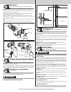
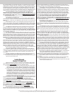
Counterbalance Cables and Rollers
Tools: None
6
NOTE: TorqueMaster
®
counterbalance cable drum assemblies are marked right and left hand.
WARNING WARNING
FAILURE TO ENSURE TIGHT FIT OF CABLE LOOP OVER MILFORD PIN COULD
RESULT IN CABLE COMING OFF THE PIN, ALLOWING THE DOOR TO FALL, POS-
SIBLY RESULTING IN SEVERE OR FATAL INJURY.
Uncoil the counterbalance cables from the drum assemblies, making sure you place the left
hand cable loop on the left hand milford pin of the bottom bracket and the right hand cable loop
on the right hand milford pin of the bottom bracket.
NOTE: Check to ensure cable loops fits tightly over the milford pins.
Insert a roller into the bottom brackets and another into the #1 end hinges at the top of the
bottom section.
NOTE: Verify astragal (bottom seal) is aligned with door section. If there is more than 1/2”
excess astragal on either side, trim astragal even with door section.
Bottom Section
Tools: Level, Wooden shims (if necessary)
7
Center the bottom section in the door opening. Level the section using wooden shims (if neces-
sary) under the bottom section.
Vertical Tracks
Tools: Power Drill, 3/16” Drill bit, 7/16” Socket driver, Tape measure,
Level, Step ladder
8
IMPORTANT: THE TOPS OF THE VERTICAL TRACKS MUST BE LEVEL FROM SIDE TO SIDE. IF
THE BOTTOM SECTION WAS SHIMMED TO LEVEL IT, THE VERTICAL TRACK ON THE SHIMMED
SIDE MUST BE RAISED THE HEIGHT OF THE SHIM.
Position the left hand vertical track assembly over the rollers of the bottom section. Make sure
the counterbalance cable is located between the rollers and the door jamb. Drill 3/16” pilot holes
into the door jamb for the lag screws.
Loosely fasten jamb brackets and flag angle to the jamb using 5/16” x 1-5/8” lag screws.
Tighten lag screws, securing the bottom jamb bracket to jamb, maintain 3/8” to 5/8” spacing
between the bottom section and vertical track. Hang cable drum over flag angle. Repeat for
other side.
Stacking Sections
Tools: Power drill,7/16” Socket driver
9
NOTE: Make sure hinges are flipped down, when stacking another section on top.
Place rollers into end hinges of remaining sections.
With assistance, lift second section and guide rollers into the vertical tracks. Lower section until
it is seated against bottom section. Flip hinges up. Fasten intermediate hinge(s) first; then end
hinges using 1/4”-14 x 5/8” self tapping screws. Repeat for other sections, except top section.
IMPORTANT: PUSH & HOLD THE HINGE LEAFS SECURELY AGAINST THE SECTIONS WHILE SE-
CURING WITH 1/4”-14 X 5/8” SELF TAPPING SCREWS. THERE SHOULD BE NO GAP BETWEEN
THE HINGE LEAFS AND THE SECTIONS.
Top Brackets
Tools: Power drill, 7/16” Socket driver
10
To install the top brackets, align the top holes in the top bracket base with the second set of
holes in the end cap of the top section. Fasten to section using (4) 1/4”-14 x 5/8” self tapping
screws. Secure the top bracket slide to the bracket base loosely using (2) 1/4”-20 x 5/8” car-
riage bolts and (2) 1/4”-20 flange hex nuts. The bracket will be tightened and adjusted later, in
step, Adjusting Top Brackets. Insert roller into top bracket slide. Repeat for other side.
U-bar
Tools: Power drill, 7/16” Socket driver, Tape measure
11
NOTE: If a u-bar is supplied, complete this step.
Place the 3” u-bar over the top rib of the top door section. Fasten each end of the u-bar to the
end cap with (2) 1/4”- 20 x 11/16” self drilling screws. Fasten center of the u-bar to the rib us-
ing (2) 1/4”-14 x 5/8” self tapping screws, one 6” to the left and one 6” to the right of the center
line of the top door section.
U-bar Asymmetrical
Tools: Power drill, 7/16” Socket driver, Tape measure
12
NOTE: If an asymmetrical u-bar is supplied, complete this step.
Place the 3” asymmetrical u-bar over the top rib of the top door section. Fasten each end of the
u-bar to the end cap with (2) 1/4”- 20 x 11/16” self drilling screws. Fasten center of the u-bar
to the rib using (2) 1/4”-14 x 5/8” self tapping screws, one 6” to the left and one 6” to the right
of the center line of the top door section.
Fasten both walls of the u-bar using (2) 1/4”-14 x 5/8” self tapping screws every 30-36 inches.
(Approximately 18 self tapping screws per 18’ u-bar)
Operator Bracket
Tools: Power drill, 7/16” Socket driver, Phillips head screwdriver, Vice
clamps, Tape measure
13
NOTE: If you’re installing a trolley operator, the operator bracket must be mounted and secured
prior to installing top section.
IMPORTANT: WHEN CONNECTING A TROLLEY TYPE GARAGE DOOR OPENER TO THIS DOOR, A
WAYNE-DALTON OPERATOR/ TROLLEY BRACKET MUST BE SECURELY ATTACHED TO THE TOP
SECTION OF THE DOOR, ALONG WITH ANY U-BARS PROVIDED WITH THE DOOR. THE INSTAL-
LATION OF THE OPERATOR MUST BE ACCORDING TO MANUFACTURER’S INSTRUCTIONS AND
FORCE SETTINGS MUST BE ADJUSTED PROPERLY.
Prior to installing top section, locate the center of the top section and seat the operator bracket
on top of the top section. For retro fit applications, the operator bracket must be aligned with an
existing operator and positioned on top section so it bridges the transition point of the section
thickness. Install (2) #12 x 1/2” phillips head screws on the back side of operator bracket.
Clamp operator bracket to u-bar (if supplied) with vice clamps. Attach (5) 1/4” - 14 x 5/8” self-
tapping screws to the operator bracket. Remove vice clamps.
NOTE: If a u-bar was installed, you can use two of the 1/4” - 20 x 11/16” self-drilling screws
previously used to attach the u-bar instead of two 1/4”-14 x 5/8” self-tapping screws when
attaching operator bracket to u-bar.
3
Please Do Not Return This Product To The Store. Contact your local Wayne-Dalton dealer. To find your local Wayne-Dalton dealer,
refer to your local yellow pages business listings or go to the Find a Dealer section online at www.wayne-dalton.com