


19
Please Do Not Return This Product To The Store. Contact your local Wayne-Dalton dealer. To find your local Wayne-Dalton dealer, refer to your
local yellow pages/business listings or go to the Find a Dealer section online at www.wayne-dalton.com
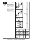
Tools Needed:
INSTALLATION
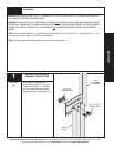
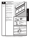
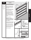
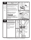
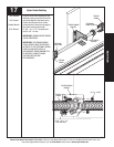
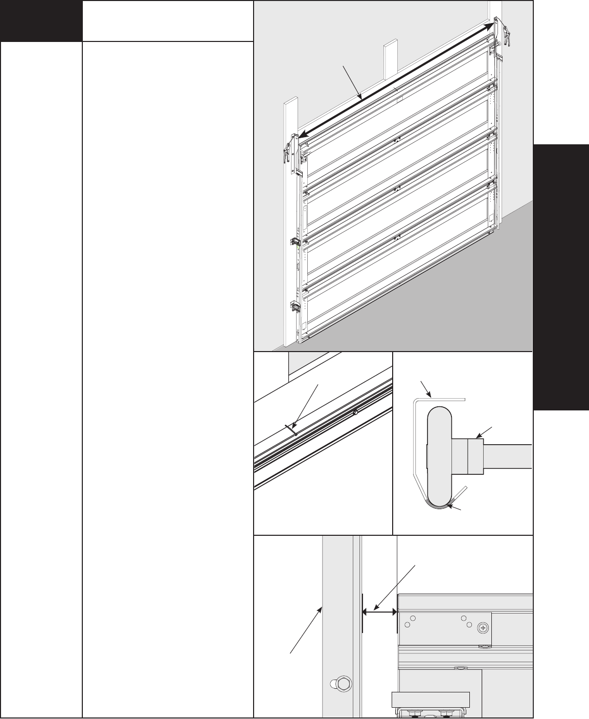
Top Section
Place the top section in the opening
and vertically align with lower sections.
Temporarily secure the top section by
driving a nail in the header near the
center of the door and bending it over
the top section.
Now flip up hinge leaf against section,
fastening center hinges first, and end
hinges last. (Refer to Step 6).
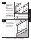
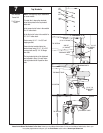
When installing a door with a torsion
counterbalance system, vertical
track alignment is critical. Position
flagangle between 1-11/16” (43 mm)
to 1-3/4” (44 mm) from the edge of
the door. Tighten the bottom lag screw.
Flagangles must be parallel to the door
sections.
Repeat for opposite side.
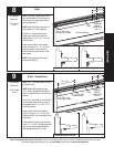
IMPORTANT: THE DIMENSION
BETWEEN THE FLAGANGLES MUST BE
DOOR WIDTH PLUS 3-3/8” (86MM) TO
3-1/2” (89 MM) FOR SMOOTH, SAFE
DOOR OPERATION.
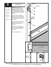
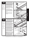
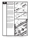
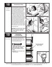
Complete the vertical track installation
by securing the center jamb bracket(s)
and tightening the other lag screws.
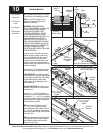
Push the vertical track against the
rollers so that the rollers are touching
the deepest part of the curved side of
the track (see illustration). Tighten all
the carriage bolts and nuts.
Repeat for opposite side.
11
Hammer
Tape Measure
Power Drill
7/16” Socket
Driver
1-11/16” TO 1-3/4”
FLAGANGLE
TOP
SECTION
NAIL
ROLLER
VERTICAL TRACK
ROLLER AGAINST
VERTICAL TRACK
TOP SECTION
DOOR WIDTH
+3-3/8” TO 3-1/2”