


-3-
WIND LOAD POST
INSTALLATION INSTRUCTIONS
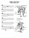
Step 6:
Place the post assembly into position by lowering the top plate
extension into the notch in the header lock bracket until the top plate
extension seats in the bottom of the notch. Allowing the outer post
to slide down the inner post, insert the 1/2-13 x 3-1/2” bolt at the
bottom of the outer post into the hole in the fl oor. Ensure the bolt is
fully inserted into the fl oor. the nut on the underside of the bottom
lock plate must rest on the fl oor.
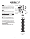
Step 7:
Beginning at the top hinge, place the strap over the post as shown in
fi gure 3. Align the holes in the ends of the strap over the tube in the
hinge and insert a 5/16” hitch pin as shown. Raise the back of the
strap until the strap is perpendicular to the post. Connect the strap
to the post with (1) 5/16-12 x 1” self drilling screw and fl at washer
1/4” above the strap on the garage side of the post and 1/4” below
the strap on the door side of the post as shown. Do not tighten the
screws against the strap. Repeat for the remaining straps. The
bottom locking strap should be located at the half hinge location
installed in step 5.
NOTE: The strap is designed to slide freely between the screws
allowing movement of the door relative to the post. Do not place the
screws through the strap or tighten the screws too tight restricting
movement.
After all of the straps have been installed, check the post to make
sure it is secure by lifting up on the post. If the post raises out of
the header lock bracket, check the location of the screws above and
below the straps. The garage side screws must be located above the
strap as shown in the fi gure 4.
Storage instructions and decal installation continued on page 4.
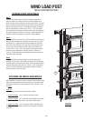
FIGURE 4
FIGURE 3
(4) 1/4-14 x 5/8”
SELF-TAPPING SCREWS
CENTER HINGE
(2) 5/16-12 x 1”
SELF DRILLING
SCREWS W/5/16
FLAT WASHER
5/16”
HITCH PIN
ALUMINUM POST
LOCKING
STRAP
COMPLETED INSTALLATION
ON (4) SECTION DOOR