


Please Do Not Return This Product To The Store. Contact your local Wayne-Dalton dealer. To find your local Wayne-Dalton dealer,
refer to your local yellow pages business listings or go to the Find a Dealer section online at www.Wayne-Dalton.com
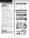
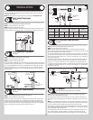
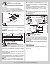
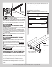
hole onto the center stile. Drill 1/16” pilot holes at the marked hole locations. Fasten both lift
handles to the center stile using #10 X 5/8” pan head self tapping screws.
If the door came with two sets of lift handles repeat the same process for the other lift
handles.
Lock section Lock section
(2) #10 X 5/8” Pan
head self tapping
screws
(4) #10 X 5/8” Pan
head self tapping
screws
Center line Center line
Vertical
line
Vertical
line
Lift
handle
Lift
handle
Lift
handle
Center stile
Center
stile
Center stileCenter stile
3-7/8” 3-7/8”
Horizontal
line
Horizontal
line
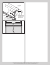
Lift handles
Bottom section
Typical placement of lift
handles referenced on
single wide doors
Lock
section
Typical placement of lift handles referenced on double wide doors
20” Minimum to
30” Maximum
20” Minimum to 30” Maximum
Pull handle
Lift handles
Bottom
section
Lock
section
Pull handle Pull handle
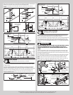
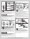
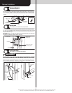
Pull Handles
Tools: Tape Measure, Pencil, Power Drill, 1/16” Drill Bit
6
Locate and mark the horizontal and vertical center on the bottom rail of the bottom section,
on single car doors.
Center the pull handle using the vertical and horizontal lines as referenced on the bottom
section rail. Using the pull handle as a template, mark the two hole locations in the pull
handle onto the horizontal line of the bottom section rail. Drill 1/16” pilot holes at the marked
hole locations. Fasten pull handle(s) using (2) #10 X 5/8” pan head self tapping screws.
If your door came with two pull handles, locate them directly below the lift handles and
repeat the installation process.
Bottom section
(2) #10 X 5/8” Pan
head self tapping
screws
Bottom rail
Center stile
Pull handle
Lift handles
Bottom section
Typical placement of pull
handle referenced on
single wide doors
Lock
section
Typical placement of pull handles referenced on double wide
20” Minimum to
30” Maximum
20” Minimum to 30” Maximum
Pull handle
Lift handles
Bottom
section
Lock
section
Pull handle Pull handle
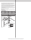
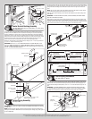
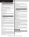
Bottom Corner Brackets
Tools: Power drill, 7/16” Socket driver
7
NOTE: The bottom section can be identified by the smallest graduated edge hinge of the
factory installed graduated edge hinges, see Parts Breakdown on page 2
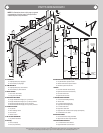
Locate the left hand bottom corner bracket. Align the bottom corner bracket horizontally with
the top edge of the factory attached bottom corner bracket. Also align the bottom corner
bracket vertically with the left edge of the bottom section. Attach the bottom corner bracket
using (4) 1/4”- 20 x 11/16” self drilling screws and (1) 1/4” - 20 x 5/8” tamper proof screw,
as shown.
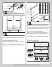
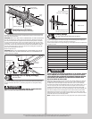
WARNING WARNING
FAILURE TO ENSURE TIGHT FIT OF CABLE LOOP OVER MILFORD PIN COULD
RESULT IN COUNTERBALANCE LIFT CABLE COMING OFF THE PIN, AL-
LOWING THE DOOR TO FALL, POSSIBLY RESULTING IN SEVERE OR FATAL
INJURY.
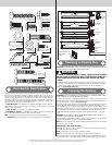
Uncoil the counterbalance cables. Place clevis pin into the inside tab of the bottom corner
bracket and slide the cable loop of the counterbalance lift cable onto pin. Continue sliding
clevis pin thru the outside tab of the bracket. Place a washer onto mildford pin and secure in
place using a cotter pin, as shown.
Insert a short stem track roller into the factory attached bottom corner brackets and another
into the #1 graduated end hinges at the top of the bottom section. Repeat for other side.
NOTE: Larger doors will use long stem track rollers with double graduated end hinges.
NOTE: Verify bottom weather seal is aligned with bottom section. If there is more than 1/2”
excess weather seal on either side, trim weather seal even with bottom section.
Short stem
track roller
Left hand bottom
corner bracket
Right hand bottom
corner bracket
(4) 1/4” - 20 x 11/16”
Self drilling screws
(1) 1/4” - 20 x 5/8”
Tamper proof screw
Counterbalance
lift cable
Bottom
weather
seal
Washer
Cotter pin
Left hand bottom corner bracket
Clevis
pin
Bottom rib
Roller
Factory attached
bottom bracket
Counterbalance
cable
Washer
Cotter
pin
Clevis
pin
Bottom section
astragal
Inside
tab
NOTE: The
bottom bracket
is not shown in
illustration, for
clarity purposes.
Outside tab
7