


idrive™ models: 3660-372, 3661-372, 3662-372,
3760-372, 3751-372.
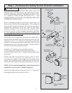
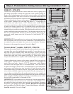
Uncoil wires from photoelectric sensors and route wires up garage wall
and along door header towards the right side of the opener
(see Fig. 3 ).
Route wires behind torque tube and tack wires in place with insulated
staples (not supplied).Take care to run wires in a location where they will
not interfere with the operation of the door and do not staple through wire.
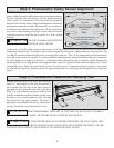
Connect photoelectric sensors to the opener terminal block on right side
of the opener. Separate wire ends and strip about 1/2” of insulation off
each of the wire ends. Insert a 3/32” (2.5mm) max. width flathead
screwdriver into the lower hole #1 of the terminal block. Twist screwdriver
to open wire clamp in upper hole #1 of terminal block. Insert both sender
and receiver solid white wires into upper hole #1 until the wires bottom
out and release screwdriver tension. Insert both sender and receiver wires
(white with black stripe) into upper hole #2 by the same process on lower
hole #2 of terminal block. Be sure to observe polarity. Once wires are
connected, install jumper on to the left most set of pins labeled “PE” of
the opener.
IMPORTANT! Keep sender/receiver wires away from moving members.
Pull on external wires to test for secure connection. Check that the wires
are stapled in place and staples have not cut wire insulation. Reconnect
the power to the garage door opener. Proceed to Step 3.
5
Step 2: Photoelectric Safety Sensor Wiring Installation For:
Torsion idrive™ models: 3651-372, 3750-372.
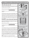
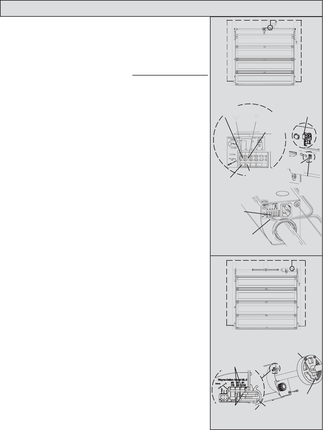
To locate the terminal block for the infrared sensor sender/receiver wires,
you must first move the right hand gear assembly. Loosen the set screw
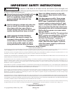
and slide the gear assembly away from the opener. Uncoil wires from
photoelectric sensors and route wires up garage wall and along door header
towards the right side of the opener (see Fig. 4). Route wires behind
torque tube and tack wires in place with insulated staples (not supplied).
Connect photoelectric sensors to the opener terminal block on right side
of the opener. Separate wire ends and strip about 1/2” of insulation off
each of the wire ends. Insert a 3/32” (2.5mm) max. width flathead
screwdriver into the upper hole #1 of terminal block. Twist screwdriver
to open wire clamp in lower hole #1 of terminal block. Insert both sender
and receiver solid white wires into lower hole #1 until the wires bottom
out and then release screwdriver tension. Insert both sender and receiver
wires (white with black stripe) into lower hole #2 by the same process. Be
sure to observe polarity. Keep the sender and receiver wires straight and
organized by wrapping them around the backside of the opener and securing
them using the cord clip (adhesive backed) provided.(Insure the surface
the cord clip is attached to is clean and oil free.
IMPORTANT! Keep sender/receiver wires away from moving members.
Pull on external wires to test for secure connection. Check that the wires
are stapled in place and staples have not cut wire insulation. Reconnect
the power to the garage door opener. NOTE: Reinstall the right hand
gear assembly onto the drive gear. Ensure that the gear assembly is
installed correctly. Proceed to Step 3
.
White wires
with black
stripe
Solid white
wires
Right hand
gear assembly
Set screw
Insert screw
driver into
lower hole #1
Jumper
installed
Jumper
FIG. 3 Wire Routing
Insert wires
into lower holes
Insert screwdriver
into upper holes
Cord clip
Insert wires
into upper
hole #2
Insert wires
into upper
hole #1
Insert screw
driver into lower
hole #2
Pins
labeled
“PE”
idrive™
FIG. 4 Wire Routing
Torsion idrive™