


3
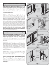
Step 2: Outside Lock Handle Assembly
8000/PR9000 & PR9050 Series doors (see Fig. 4),
align the outside handle assembly with the handle point-
ing towards the fl oor and insert the assembly through
the previously drilled 3/4” diameter holes in the section.
Secure the outside lock handle to the section with (2)
#10 phillips head screws.
9000 Series & Wood doors (see Fig. 5), align the out-
side handle assembly with the handle pointing towards
the fl oor and insert the assembly through the previously
drilled 3/4” diameter holes in the section. With the
outside lock placed in the section, place the center lock
stile over the shank of the outside lock handle, secure
the center lock stile with foam tape (8300/8500 Series
& Wood doors will use the lock backup plate with no
foam tape). Secure the outside lock handle to the sec-
tion by placing the (2) #10 phillips head machine screws
through the lock stile into the lock section. NOTE:
Before proceeding to the next step its recommended
that the outside handle be locked.
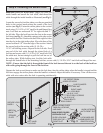
Step 3: Inside Handle Assembly
PRE-PUNCHED
HOLES
SHANK
INSIDE
HANDLE
HANDLE
CENTER
STILE
HANDLE
INSIDE
HANDLE
SHANK
Fig. 6
Fig. 7
8000/8100/8200 & 9000 Series doors (see Fig.6), po-
sition the inside handle over the shank of the outside
handle, fl ush against the center stile. Align the holes
in the handle with the pre-punched holes in the center
stile, then turn the handle clockwise to secure with (2)
#8 screws.
8300/8500 Series & Wood doors ( see Fig.7), position
the inside handle over the shank of the outside handle,
fl ush against the lock backup plate. Align the holes
in the handle with the pre-punched holes in the lock
backup plate, then turn the handle clockwise to secure
with (2) #8 screws.
NOTE: When securing the inside handle bracket,
be sure not to over tighten the screws or damage to
the inside handle may occur.
NOTE: Follow the Main Installation Instruction
Manual to install the door sections and vertical track
before you install the remainder of the lock parts.
After the sections and track are installed, continue
with Step 4.
BACKUP PLATE
PRE-PUNCHED
HOLES
Fig. 4
Fig. 5
OUTSIDE
HANDLE
3/4” DIA.
HOLES
#10 PHILLIPS
HEAD SCREWS
HANDLE
SHANK
3/4” DIA.
HOLES
OUTSIDE
HANDLE
#10 PHILLIPS
HEAD SCREWS
HANDLE
SHANK
FOAM TAPE
CENTER
STILE
(2) #8 SCREWS
(2) #8 SCREWS