


22
Step 1: Installing the ECR Lock
CAUTION
DO NOT DRILL LOCK SEC-
TION OR INSTALL LOCK ON DOORS WITH
OPENERS. THE DOOR AND/ OR OPENER MAY
BE DAMAGED IF THE OPENER IS USED WHILE
THE DOOR IS LOCKED.
NOTE: Common practice for doors with the odd
number of raised panels is to mount the lock towards
the right side of the section when looking out.
IMPORTANT: Remove all burrs from the drilled
holes before installing the lock to the section.
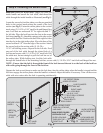
8000/8100/8200/PR9000 & PR9050 Series doors (see
Fig.1), place the lock section face down on (2) padded
sawhorses for a single car door or (3) padded sawhorses
for a double car door. Locate the (3) hole pattern in the
center stile of the lock section. Use the (3) holes as a
template to drill (3) 1/8” diameter holes through the
section. Flip the section over, face up. With the section
face up, enlarge all (3) holes to 3/4” diameter, pay close
attention not to drill complete through section into
center stile.
NOTE: Do not drill through or enlarge holes in the
center stile.
8300/8500 Series & Wood doors (see Fig.2), place
the lock section face up on (2) padded sawhorses for
a single car door or (3) padded sawhorses for a double
car door. Locate the middle of the center stile, measure
the distance from the end of the section to the middle of
the center stile. Turn the section face down, transfer the
measurement and mark a light vertical line, then mark a
horizontal line at half the section height. Align the 7/16”
diameter hole of the lock backup plate at the intersection
point of the horizontal and vertical marks, use the lock
backup plate as a template to mark the (3) holes, remove
the lock backup plate and drill (3) 3/4” diameter holes
through the section.
9000 Series doors (see Fig.3), place the lock section
face up on (2) padded sawhorses for a single car door or
(3) padded sawhorses for a double car door. Locate the
middle of the center stile, measure the distance from the
end of the section to the middle of the center stile. Turn
the section face down, transfer the measurement and mark a light vertical line. Align the center of the lock stile
with vertical mark, use the lock stile as a template to mark the (3) holes, remove the lock stile and drill (3) 3/4”
diameter holes through the section.
7/16” DIA.
HOLE
FACE DOWN
FACE DOWN
Fig. 2
Fig. 3
FACE DOWN
FACE UP
Fig. 1
(3)PRE-PUNCHED
HOLES
CENTER STILE
(3) 3/4” DIA.
HOLES
VERTICAL
MARK
HORIZONTAL
MARK
(3) 3/4”DIA.
HOLES
VERTICAL
MARK
LOCK STILE
(3) 3/4”DIA.
HOLES
LOCK BACKUP
PLATE
1/2 THE
SECTION
HEIGHT