


5
Operating Instructions and Parts Manual Deep Well Submersible Pump
www.waynepumps.com
Installation (Continued)
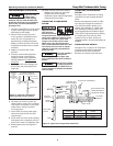
To prevent sand-
locking pump,
follow this procedure when starting
pump for the first time. Do NOT start
pump with discharge valve completely
open unless you have followed this
procedure first.
1. Connect a pipe elbow, a short length
of pipe, and a gate valve to pump
discharge (at well head).
2. Mount motor control box (for a
3-wire pump) or fused disconnect
switch (for a 2-wire pump) in a
permanently weatherproof place.
Make sure that controls will not be
subjected to extreme heat or excess
moisture.
3. Make sure controls are in OFF
position.
4. Connect motor leads and power
supply to motor control box or
magnetic starter (see Installation
Wiring Diagrams). Do NOT start
pump yet.
5. Open gate valve on discharge one-
third of the way. Start pump (see
Figure 8).
6. Let water run until it is clear. (To
check solids in water, fill a container
with water from pump. If any solids
settle after a minute, continue
running pump.)
7. Once water runs clear, open gate
valve two-thirds of the way and
repeat step 6.
8. Once water runs clear at this setting,
open gate valve completely and run
pump until water is completely clear.
9. Remove gate valve (see Figures 9
and 10).
10. Install sanitary well seal or pitless
adapter unit, well unit, electrical
conduit and surface piping.
Installation must meet all applicable
national and local codes.
CONNECTING TO TANK/WATER
SYSTEM
High pressure and
tank explosion
hazard! To prevent
overpressurization, install a pressure
relief valve capable of releasing pump
air flow at 75 psi (517.1 kPa) when
using air-over-water pressure tank.
When using a pre-charged pressure
tank, install a pressure relief valve that
will release entire air flow at 100 psi
(690 kPa). Install this valve between
pump and tank.
Use only plumber's
seal tape on
threaded joints in plastic pipe. Pipe
joint compound CAN cause cracking in
plastics.
Do NOT allow pump
or piping system to
freeze. Failure to do so COULD result in
serious damage to equipment and WILL
void warranty.
CONTROL
CENTER
OR
ELECTRICAL
DISCONNECT
BOX
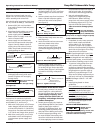
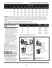
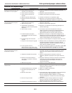
TEMPORARY WIRING
TO CONTROL CENTER OR
ELECTRICAL DISCONNECT BOX
TEMPORARY PIPING
GATE VALVE
PUMP IN WELL
Figure 8 - Temporary connections
while cleaning well for startup
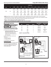
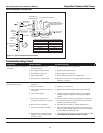
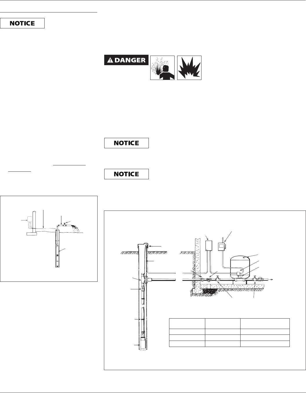
CONNECTING TO TANK/WATER
SYSTEM
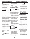
See Figure 9 for illustration of piping
connections to pre-charged pressure
tanks.
Before starting pump, check to make
sure that pre-charged air pressure is
2 psi (13.8 kPa) below pump cut-in
setting. (For example, in a tank used
with a 30-50 psi pressure switch, the
pre-charged pressure should be 28 psi
[193.1 kPa].) Adjust pressure by adding
or releasing air from the tire valve
located on top of tank. Check pre-
charged pressure annually and adjust as
needed.
STANDARD TANK HOOKUP
See Figure 10, on page 6, for illustration
of piping connections to standard
pressure tank as well as distance
between air release ports and tank.
VENTILATED
WELL CAP
SUBMERSIBLE
CABLE
PITLESS
ADAPTOR
CHECK
VALVE
TAPE CABLE
TO PIPE
PUMP
CONTROL BOX
(3 WIRE MODELS)
ELECTRICAL DISCONNECT
PRE-CHARGED TANK
PRESSURE SWITCH
PRESSURE GAUGE
TO HOUSE
SERVICE
RELIEF VALVE
UNION
GATE VALVE
CUT IN CUT OFF Pre-charge Tank
PSI (kPa) PSI (kPa) PSI (kPa)
20 (137.9) 40 (275.8) 18 (124.2)
30 (206.8) 50 (344.7) 28 (193.1)
40 (275.8) 60 (413.7) 38 (262)
Figure 9 - Typical Pre-charged Tank Installation