


3
www.waynepumps.com
Electrical System
(Continued)
Use only control
box specified
for your pump. Make sure motor and
control box match (see Table 4, on page
3). Failure to do so WILL void warranty.
4. Install circuit protection and
component protection in compliance
National Electrical Code, Part 1.
Consult with appropriate code
officials for more information on
how to do this.
If main overload trips, look for the
following:
1. Shorted capacitor
2. Voltage problems
3. Overloaded or locked pump.
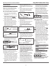
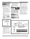
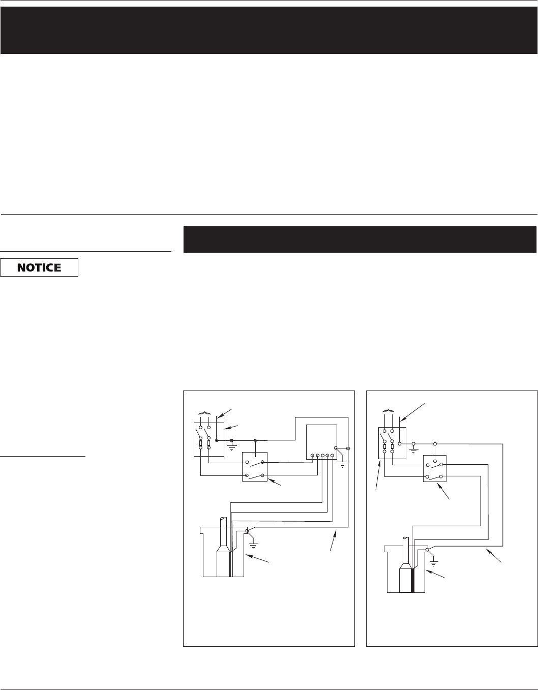
Single Phase, 2 Wire
Two-wire pumps have two power supply
wires and one ground wire (Green). A
control box is not required. See Figure
1b for correct hookup for 230 volt
2-wire motors only.
Operating Instructions and Parts Manual
Deep Well Submersible Pump
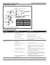
Cable Size
Volts HP
14
(2 mm
2
)
12
(3 mm
2
)
10
(5 mm
2
)
8
(7 mm
2
)
6
(13 mm
2
)
4
(21 mm
2
)
3
(25 mm
2
)
2
(34 mm
2
)
1
(41 mm
2
)
0
(50 mm
2
)
1/2 400
(121.9)
650
(198.1)
1020
(310.9)
1610
(490.7)
2510
(765)
3880
(1182.6)
4810
(1466.1)
5880
(1792.2)
7170
(2185.4)
8720
(2657.9)
230 3/4 300
(91.4)
480
(146.3)
760
(231.6)
1200
(365.8)
1870
(570)
2890
(880.9)
3580
(1091.2)
4370
(1332)
5330
(1624.6)
6470
(1972.1)
1 250
(76.2)
400
(121.9)
630
(192)
990
(301.8)
1540
(469.4)
2380
(725.4)
2960
(902.2)
3610
(1100.3)
4410
(1344.2)
5360
(1633.7)
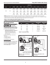
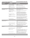
NOTE: Specified maximum wire lengths are valid with motor voltage greater than or equal to 95% of service entrance
voltage and motor running at maximum nameplate amperes. If service entrance voltage is at least motor nameplate voltage
under normal load conditions, 50% additional length is permissible for all sizes shown.
Table 3 - Power supply wire (cable) length in feet (m)
1 phase, 2 or 3 wire cable, 60 Hz (copper wire size—service to motor)
HP Voltage Wires
Pump Model
No.
Control Box
No.
1/2 230 3 T50S10-2 16965-002
1/2 230 2 T50S10-2 None
1/2 115 2 T51S10-4 None
3/4 230 3 T75S10-2 16966-002
3/4 230 2 T75S10-4 None
1 230 3 T100S10-2 16967-002
Table 4 - Control box chart
L1 M1
M2L2
CONTROL
BOX
L1L2RYB
FUSED
DISCONNECT
SWITCH
115V or
230V LINE
GROUND
RED
YELLOW
BLACK
PRESSURE
SWITCH
WELL
CASING
GROUND
L1 M1
M2L2
FUSED
DISCONNECT
SWITCH
TO LINE
GROUND
RED
BLACK
PRESSURE
SWITCH
WELL
CASING
GROUND
(GREEN)
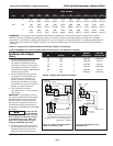
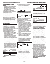
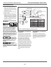
Follow color coding when
connecting control box wires.
(Yellow = Y, Red = R, Black = B)
Figure 1a - 3 wire, 1/2-1HP quick
disconnect box
Figure 1b - Single phase, 2 wire
connections