14. To reassemble, install new bearings
on the shaft. Always press against
the inner race to prevent bearing
damage. Make sure bearings are
tight against the shaft shoulders.
15. Press shaft seal into backhead.
When pressing shaft seal into place,
apply force to the cup flange. Avoid
touching the polished seal surface;
oil or scratches on this surface may
cause premature failure of the seal.
16. Press ceramic side of seal into
impeller, ceramic side out. Avoid
touching ceramic with hands as oil
may cause premature failure of the
seal. Wipe oil off both sides of seal
with a soft, lint-free cloth.
17. Reassemble unit in reverse order,
beginning with step 9.
18. After reassembly check shaft for
free rotation with screwdriver in
fan through air exit openings.
3
Operating Instructions and Parts Manual
Maintenance
(Continued)
ADDITIONAL REPAIRS
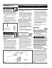
To replace bearings, shaft seal, gaskets,
rotor, follow the instructions listed below.
1. Disconnect electrical cord from
power supply.
2. Relieve pressure in system.
3. Disconnect inlet and outlet lines.
4. Empty water from pump housing.
5. Place pump on bench with motor
end up and remove brushes as
described in BRUSH REPLACEMENT
instructions. If brushes are to be
reused, mark the location from
which each came. Replace brushes
in original orientation upon com-
pletion of repair.
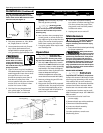
6. Remove the four cap screws hold-
ing motor housing and pump hous-
ing together. Motor housing is now
free and can be removed. Take care
not to lose commutator bearing fin-
ger spring.
7. With a screwdriver, pry the rotor-
backhead assembly out of the
pump housing.
8. Remove the impeller by turning
counter clockwise (righthand thread
on shaft). Save any washers which
were between impeller hub and
shaft.
9. Remove backhead (the bearing is
press fit into the backhead).
10. Place backhead on flat surface with
impeller side down and press out
shaft seal.
11. Place impeller on flat surface with
vane side down and with screwdriv-
er and hammer break ceramic seal
ring into several pieces and remove.
Next, remove rubber seal ring cup
from impeller.
12. Remove bearings from armature
shaft (press-fit on shaft).
13. Inspect the armature commutator
bars. The environment in which the
unit has been operating will have
influence on the condition of the
commutator. Airborne dust an dirt
will accelerate wear. A rough or
scarred appearance may dictate
having commutator reconditioned
before reassembly.
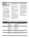
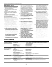
Troubleshooting Chart
Symptom Possible Cause(s) Corrective Action
Pump will not start
or run
Pump will not prime
or retain prime after
operating
Flow rate is too low
Seal leaks
1. Blown fuse
2. Low line voltage
3. Worn brushes
4. Impeller blocked
5. Defective motor
1. Air leak in suction line
2. Impeller blocked
3. Worn seal
4. Suction lift too high
5. Hose kinked or looped
6. Fittings not tight
7. Suction hose out of water
8. Clogged inlet
1. Piping or hose is fouled or
damaged
2. Low line voltage
1. Worn seal
2. Shaft grooved
3. Pump head loose on motor
1. If blown, replace with proper sized fuse or reset breaker
2. If voltage is under 108 volts, check wiring size
3. Replace brushes
4. Remove blockage
5. Replace motor or pump
1. Repair or replace suction line
2. Remove blockage
3. Replace seal
4. Lower pump
5. Straighten hose
6. Tighten fittings
7. Submerge suction hose end
8. Clean inlet
1. Clean or replace
2. If voltage is under 108 volts, check wiring size
1. Replace seal
2. Replace rotor
3. Insure proper assembly and no obstruction, tighten bolts
www.waynepumps.com


