


WATLOW IND. WATROD Modular Duct Heater Installation & Maintenance Manual
I&M NUMBER: 316-42-15-1 Page: 2
Date:6/11/2008 Rev: 2
_________________________________________________________________________________________________________________________________________________________________________________________________________________________
______
WATLOW IND.n # 6 INDUSTRIAL LOOP RD. n HANNIBAL MO, 63401n PHONE 314-221-2816 n FAX 314-221-3723
Failure of components in a temperature control loop, such as the sensor, heater control relay or main
temperature control, can result in damage to a product in process, a melt down of a heater, and / or
damaging fire.
To protect against this possibility, over temperature protection must be provided to interrupt or remove
power from the heater circuit. A bulb and capillary thermostat is not recommended for this function
since it may not respond quickly enough to adequately protect the heater. In cases where the
thermostat bulb gets too hot before the system is turned off, the thermostat bulb could rupture.
This could result in the thermostat remaining in the "ON" condition since there is insufficient
fluid to move contacts apart. We recommend the temperature protection have appropriate third party
approval, and be applied in the classification for which it was tested and approved.
3. Terminal Enclosures
Terminal enclosures should be selected to be compatible with the environment in which the heater will
be located. It is the users responsibility to determine the need for correct rating of the electrical housing.
This should be based on appropriate national and local electrical codes. Failure to use a compatible
enclosure could result in heater damage and personnel danger.
Standard terminal enclosures are designed for general purpose use and are rated NEMA 1. These
enclosures should be applied where there will be no danger of spilled liquids, dampness, dirt, and
gaseous conditions. Enclosures for wet or hazardous locations are also available, but must be installed
at the factory.
Although enclosures are supplied over the terminals, units should be located in an area that will minimize
the chance of being hit by falling or moving objects. The terminals must be protected at all times from
moisture or vapor.
In hazardous locations, (as defined in NFPA 70 NEC, Article 501) explosion resistant housings must be
used.
In order to maintain termination integrity, the terminal enclosure should be kept below 400°F
(204°C).
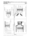
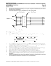
4. Orientation / Mounting
The duct heater may be mounted vertically, or horizontally, from the left to right, top or bottom. The inlet
side of the unit must be at least 48" downstream from any transition in duct size or direction, or from any
air handling equipment. See Figure 1 for locations that should be avoided.
Heaters may be ganged in parallel for nearly any total wattage desired. The temperature control
thermocouple if so equipped should be located near the work to sense
exiting air temperature. Conduct
process temperature sensing in the outlet stream away from the heater.
Minimum air velocity through the heater is 200 fpm for air temperatures approaching 800°F (412°C).
Lower velocities will jeopardize element life.
Air flow over the entire face of the heater should be uniform at the design velocity.
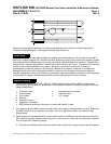
The units screw or bolt in place through the 3/8" dia. holes in the mounting flange. When installed
vertically through the top of the duct, they are self supporting when the duct is capable of supporting the
heater weight.