


Waterford TARA T25 Direct Vent Freestanding Gas Stove
7
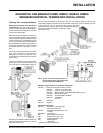
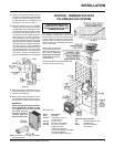
OPTIONAL FAN
INSTALLATION
for units starting with serial #
11106 to 13347 / 217000001 to present.
Fan Kit Contains:
Qty. Description
1 Fan Assembly c/w green wire attached
1 Thermodisc
1 power cord
2 2-1/4" x 20 hex nut
1) Remove the thermodisc from the bracket on
the fan assembly, do not disconnect the
wires.
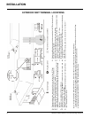
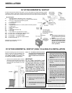
LOCATING YOUR
GAS STOVE
When selecting a location for your stove,
ensure that the clearances listed above are met
as well as ensuring that there is adequate
accessibility for servicing and proper opera-
tion.
For Vent Termination requirements, see page
10.
A) Cross Corner
B) Room Divider
C) Island
D) Flat on Wall
E) Flat on Wall Corner
F) Flush with Wall/Alcove
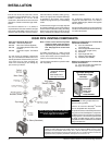
4) Remove the nylon hole plug from the control
panel.
5) Install the fan speed controller onto the
control panel and secure with nut and
washer. Connect the red and black wires
from the wire harness to speed controller.
NOTE: Speed control wires must be in the
down position when control panel is in
place.
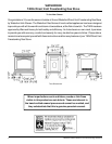
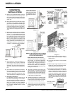
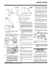
INSTALLATION
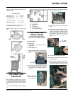
Use the minimum clearances shown in the
diagrams below:
TARA Clearances
Side Wall to Unit* A 6" / 150 mm
Back Wall to Unit B 3" / 75 mm
Unit Corner to Wall C 2" / 50 mm
Unit to Alcove Ceiling 13" / 330 mm
Max. Alcove Depth 24" / 610 mm
*If installing the side shelves, which are 6"
wide, additional space is required.
Minimum ceiling height is 47"/1294mm from
floor.
2) Remove the rear access panel on the back
of the stove by removing the 6 screws.
Take care not to cut wires when lowering
the panel.
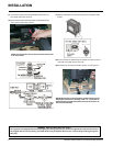
Thermodisc
Top Control Panel Assembly
Fan Speed
Controller
Rear Access Panel
secured with 6 screws
(3 on each side)
6) Push black knob onto speed control.
7) Re-attach control panel with 3 screws,
reversing step 2.
8) Mount the blower assembly in position un-
der the base of the stove and secure with
the 2 supplied bolts (2-1/4" #20 hex head)
3) Remove the Top Control Panel Assembly by
removing the three screws.