


Waterford E65-1 Emerald Direct Vent Freestanding Gas Stove 25
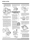
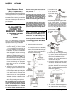
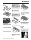
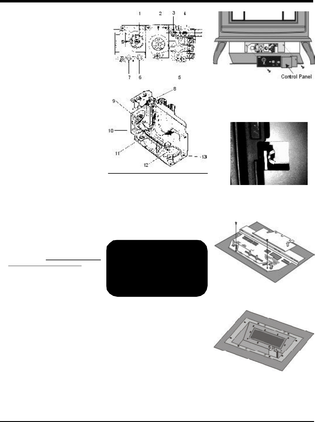
4) Carefully remove the logs, embers and
rockwool.
5) Remove burner. See diagram below.
Pilot assembly is now accessible
for steps 6) to 11).
Note: Use a magnetic type screwdriver
if possible.
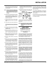
THIS CONVERSION MUST
BE DONE BY A
QUALIFIED GAS
FITTER IF IN DOUBT DO
NOT DO THIS
CONVERSION !!
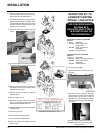
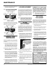
3) Open the front door. Open the right side
door and there is a cutout in the heat shield
through which can be seen a wing nut
threaded on to a stud attached to the front
door. Loosen this nut by turning it counter-
clockwise.
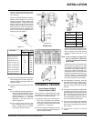
Conversion Kit Contains:
Qty. Part # Description
1 910-018 SIT Conversion Kit-50%
Turndown LP
1 910-037 LP Injector (Pilot Orifice)
1 904-641 Burner Orifice #50
1 908-175 E63/E65 Decal "Converted to
Propane"
1 908-528 Red "PROPANE" label
1 908-780 Instruction Sheet
1) Shut off the gas supply.
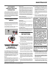
2) Open the valve door and remove the control
panel.
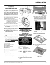
CONVERSION KIT
FROM NATURAL GAS
TO PROPANE
Model #261-969
for Emerald Gas Stoves and Gas
Inserts using SIT 820 NOVA Gas
Valve
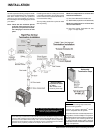
INSTALLATION
GAS PIPE
PRESSURE TESTING
The appliance must be isolated from the gas
supply piping system by closing its individual
manual shut-off valve during any pressure
testing of the gas supply piping system at test
pressures equal to or less than 1/2 psig. (3.45
kPa). Disconnect piping from valve at pressures
over 1/2 psig.
The manifold pressure is controlled by a regu-
lator built into the gas control, and should be
checked at the pressure test point.
Note: To properly check gas pressure,
both inlet and manifold pressures
should be checked using the valve
pressure ports on the valve.
1) Make sure the valve is in the "OFF" position.
2) Loosen the "IN" and/or "OUT" pressure tap(s),
turning counterclockwise with a 1/8" wide
flat screwdriver.
3) Attach manometer to "IN" and/or "OUT" pres-
sure tap(s) using a 5/16" ID hose.
4) Light the pilot and turn the valve to "ON"
position. Read manometer.
5) The pressure check should be carried out
with the unit burning and the setting should
be within the limits specified on the safety
label.
6) When finished reading manometer, turn off
the gas valve, disconnect the hose and
tighten the screw (clockwise) with a 1/8"
flat screwdriver. Note: Screw should be
snug, but do not over tighten
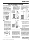
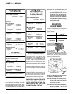
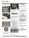
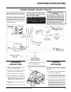
Valve Description
1) Gas cock knob
2) Manual high/low adjustment
3) Pilot Adjustment
4) Thermocouple Connection
5) Main Operator
6) Outlet Pressure Tap (Manifold Pressure)
7) Inlet Pressure Tap (Supply Pressure)
8) Pilot Outlet
9) Main Gas Outlet
10)Flange Securing Screw Holes
11)Alternative TC Connection Point
12)Thermoelectric Unit
13)Additional Valve Mounting Hole