


VIVOTEK
10 - User's Manual
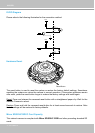
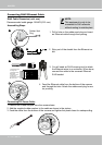
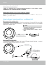
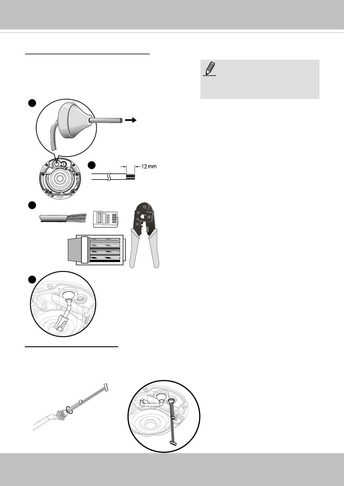
RJ45 Cable Dimension (unit: mm)
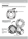
Assembling Steps
2. Strip part of the sheath from the Ethernet ca-
ble.
1. Drill a hole on the rubber seal plug and insert
an Ethernet cable through the opening.
3. You will need an RJ45 crimping tool to attach
the Ethernet wires to a connector. When done,
connect the cable to the camera’s Ethernet
RJ45 socket.
4. Feed the Ethernet cable from the bottom of the camera
and through the hole. Attach the rubber seal plug for wa-
ter proong.
Recommended cable gauge: 24AWG (0.51 mm)
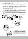
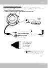
1. Remove the rubber stopper from the camera base.
2. Add the supplied rubber washer to the cable as shown in the picture.
3. Feed the cable from the bottom of the camera and tighten the plastic base for waterproong.
Connecting RJ45 Ethernet Cable
Connecting DC Power Cable
Rubber Seal
Plug
1
2
o
O
g
B
b
G
br
BR
1
2
3
4
5
6
7
8
o: white/orange stripe
O: orange solid
g: white/green stripe
B: blue solid
b: white/blue stripe
G: green solid
br: white/brown stripe
BR: brown solid
3
4
NOTE:
This equipment is only to be
connected to PoE networks
without routing to outside plant.