


9
105604
OWNER’S MANUAL
For more information, visit www.desatech.com
Built-In Installation of Blower
Accessory
1. Before replacing bottom of firebox,
remove screw holding duplex outlet to
the support bracket in the bottom of
firebox. Remove duplex outlet.
2. Clamp electrical cable into firebox
through smallest hole in outer casing
using strain relief provided.
3. Route wires from electrical box through
hole in side of heater and hole in sup-
port bracket (see Figure 12).
4. Connect wires from the electrical box
to duplex outlet. Match wire colors to
those indicated on duplex outlet. Be
sure to connect ground wire.
5. Replace duplex outlet with screw.
6. Plug blower power cord into duplex
outlet.
7. Replace bottom of firebox.
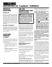
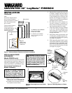
Figure 12 - Routing Blower Accessory
Power Cord for Built-In Installation
Cables From
Electrical
Source
Duplex
Outlet
Screw
Blower Power Cord
Blower
Support
Bracket
Figure 11 - Installing Plastic Bushing for
Power Cord
Plastic
Bushing
Figure 10 - Attaching Speed Control
Speed
Control
Lock Nut
Control Knob
Control
Shaft
Operating the Blower
Light your gas appliance with the blower
off. After about 15 minutes, turn the blower
on to deliver heated air at the top louvers.
The blower features a variable control which
allows you to select the speed you desire.
Note:
Periodically check the louvers of the
firebox and remove any dust, dirt, or other
obstructions.
7. Plug in blower power cord.
a. If your firebox is installed as a free-
standing unit, determine whether the
power cord will exit the left side or the
right side of the firebox. Install 1 plas-
tic bushing provided into the 1
1
/2" hole
in the floor support on the exit side.
Install the second plastic bushing pro-
vided into the 1
1
/2" hole in the outer
casing through which the power cord
will exit (see Figure 11). Route power
cord through both plastic bushings
and plug the power cord into a 3-
prong grounded wall receptacle near
the firebox.
b.If your firebox installation is re-
cessed and/or pre-wired, see Built-
In Installation of Blower Accessory,
column 2.
8. Turn on power to duplex outlet if previ-
ously turned off per the warning in step 1.
9. Check to make sure that the power cord
is completely clear of the blower wheel
and that there are no other foreign ob-
jects in blower wheel. Turn blower on
and check for operation.
WARNING: Never touch the
blower wheel while in operation.
10. Peel off the backing paper and stick the
supplied wiring diagram decal on the fire-
box bottom approximately 12" in front
of the blower.
11. Replace bottom of firebox.
Note:
Make
sure the back of the firebox bottom
slides under the rear of the firebrick (lift
the firebrick up if necessary.)
12. Reattach firebox bottom using 4 screws
removed in step 1.
Note:
Discard the remaining hardware
items.
13. Install the log set heater according to
the installation instructions supplied
with the heater.
NOTICE: A qualified electrician
must connect electrical wiring to
duplex outlet for built-in installa-
tion. Follow all local codes. In
absence of local codes follow
The
National Electrical Code ANS/
NFPA 70.
INSTALLATION
Continued
5. Install and properly test gas log heater.
Follow installation instructions in-
cluded with the vent-free gas log heater
that is being installed.
6. Replace firebox bottom and secure with
screws.
NOTICE: Most building codes do
not permit concealed gas con-
nections. A flexible gas line is
recommended to allow accessi-
bility from the firebox. The flex-
ible gas supply line connection
to the manual shutoff valve
should be accessible.
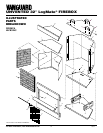
1. Remove four screws holding firebox
bottom in place.
2. Lift and remove firebox bottom (see
Figure 13, page 10).
3. If installing GA3700 Blower Accessory
(Models FB32CA and NLFB32C only),
see Installing Blower Accessory, page 8.
4. Route flexible gas line from manual
shutoff valve into firebox through side.
INSTALLING LOG HEATER IN
FIREBOX
CAUTION: Do not pick up log
base assembly by burners. This
could damage burners. Only
handle base by grates.
CAUTION: Do not remove the
metal data plates attached to the
heater base assembly. The data
plates contain important warranty
information.
Continued