


13
105190
OWNER’S MANUAL
ON
POSITION
OFF
POSITION
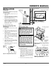
INSTALLATION
Continued
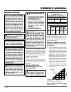
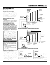
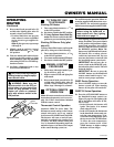
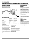
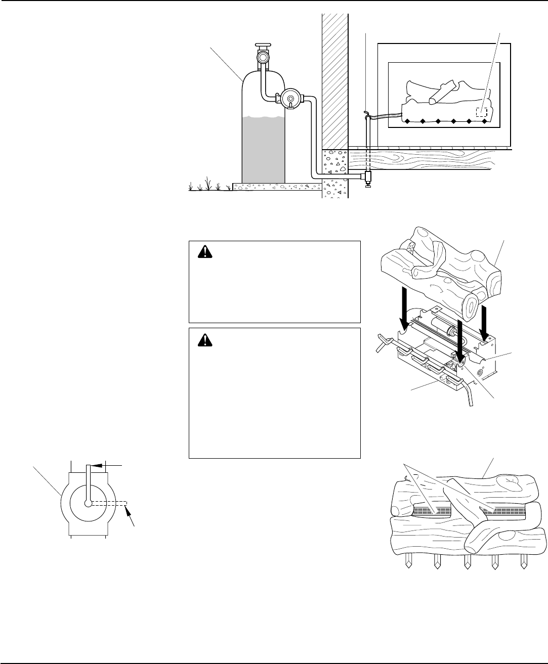
Figure 16 - Equipment Shutoff Valve
Open
Closed
Equipment
Shutoff
Valve
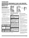
Figure 17 - Checking Gas Joints
Test Pressures Equal To or Less Than
1/2 PSIG (3.5 kPa)
1. Close equipment shutoff valve (see
Figure 16).
2. Pressurize supply piping system by ei-
ther using compressed air or opening
propane/LP supply tank valve.
3. Check all joints from propane/LP sup-
ply tank to equipment shutoff valve (see
Figure 17). Apply a noncorrosive leak
detection fluid to gas joints. Bubbles
forming show a leak.
4. Correct all leaks at once.
Pressure Testing Heater Gas
Connections
1. Open equipment shutoff valve (see Fig-
ure 16).
2. Open propane/LP supply tank valve.
3. Make sure control knob of heater is in
the OFF position.
4. Check all joints from equipment shutoff
valve to control valve (see Figure 17).
Apply a noncorrosive leak detection
fluid to gas joints. Bubbles forming
show a leak.
5. Correct all leaks at once.
6. Light heater (see Operating Heater,
pages 14 through 16). Check all other
internal joints for leaks.
7. Turn off heater (see To Turn Off Gas to
Appliance, page 15).
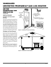
Control Valve Location
Propane/LP
Supply Tank
Equipment Shutoff
Valve
A
U
T
O
O
F
F
O
N
O
F
F
P
I
L
O
T
O
N
H
I
L
O
H
I
L
O
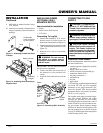
WARNING: Failure to position
the parts in accordance with these
diagrams or failure to use only
parts specifically approved with
this heater may result in property
damage or personal injury.
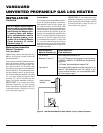
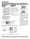
INSTALLING LOGS
It is very important to install the logs exactly
as instructed. Do not modify logs. Only use
logs supplied with heater.
1. Place one-piece log set on grate to fit
as illustrated in Figure 18. Make sure
middle section at bottom of log set is
seated into “U”-shaped cutout in cen-
ter of chassis (see Figure 18). Log will
fit securely on chassis.
IMPORTANT:
Make sure log does not cover any
burner ports.
2. Place lava rock around base of heater.
CAUTION: After installation
and periodically thereafter, check
to ensure that no flame comes in
contact with any log. With the
heater set to High, check to see if
flames contact any log. If so, re-
position logs according to the
log installation instructions in this
manual. Flames contacting logs
will create soot.
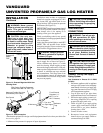
Figure 18 - Installing Vintage Oak One-
Piece Log Set
Figure 19 - Installing Vintage Oak One-
Piece Log set (Top View)
One Piece Log SetBurner
Ports
One Piece Log Set
Burner
"U"-shaped
Cutout in
Chassis
Chassis