


11
105190
OWNER’S MANUAL
9. Drill holes at marked locations using
3/16" drill bit.
10. Attach base assembly to fireplace floor
using two masonry screws (in hardware
package).
A
U
T
O
O
F
F
O
N
O
F
F
P
I
L
O
T
O
N
H
I
L
O
H
I
L
O
INSTALLATION
Continued
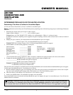
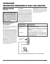
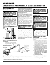
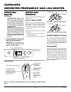
Figure 11 - Attaching Flexible Gas Hose
to Heater
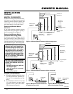
Figure 12 - Attaching Base Assembly to
Fireplace Floor
Fitting
Flexible Gas
Hose (if allowed
by local codes)
Masonry Screw
Mounting
Flanges
Continued
INSTALLING GWMS2
(OPTIONAL) WALL
MOUNTED SWITCH
Items Included for Installation
• Switch
• Switch Cover (With Screws)
• 25 Ft. Wire
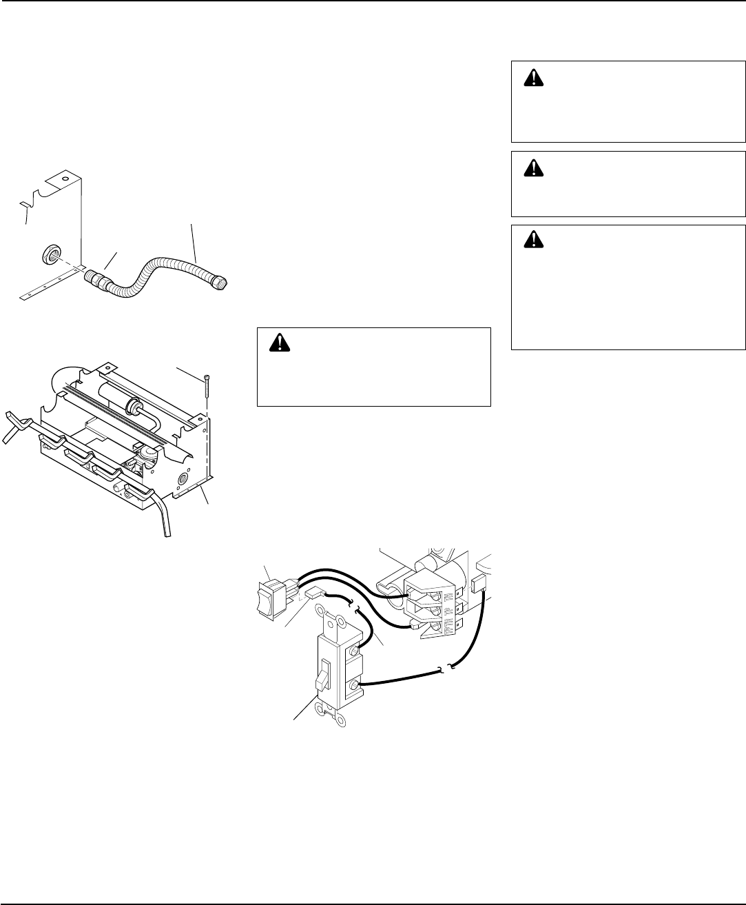
Connecting To Log Set
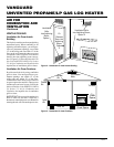
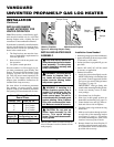
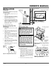
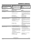
1. Connect one terminal of 25 ft. wire to
bottom contact of switch located on
heater front control panel (see Figure 13).
2. Connect remaining wire terminal to the
“TH” terminal on the control valve (see
Figure 13).
3. Route the 25 ft. wire to a convenient
location.
WARNING: Do not connect
the switch to a power source.
Electrical shock and/or fire haz-
ard will occur.
IMPORTANT:
The wire may be shortened
but must not be lengthened.
4. Connect one bare wire end to each of
the terminals of the provided wall
switch.
5. Install the wall switch and cover in the
wall.
CONNECTING TO GAS
SUPPLY
WARNING: A qualified service
person must connect heater to
gas supply. Follow all local codes.
CAUTION: Never connect
heater directly to the propane/LP
supply. This heater requires an
external regulator (not supplied).
Install the external regulator be-
tween the heater and propane/LP
supply.
Installation Items Needed
Before installing heater, make sure you have
the items listed below.
• external regulator (supplied by installer,
see above)
• piping (check local codes)
• sealant (resistant to propane/LP gas)
• equipment shutoff valve *
• test gauge connection *
• sediment trap
• tee joint
• pipe wrench
* A CSA design-certified equipment shutoff
valve with 1/8" NPT tap is an acceptable
alternative to test gauge connection. Pur-
chase the optional CSA design-certified
equipment shutoff valve from your dealer.
See Accessories, page 24.
The installer must supply an external regu-
lator. The external regulator will reduce
incoming gas pressure. You must reduce
incoming gas pressure to between 11 and 14
inches of water. If you do not reduce incom-
ing gas pressure, heater regulator damage
could occur. Install external regulator with
the vent pointing down as shown in Figure
14, page 12. Pointing the vent down protects
it from freezing rain or sleet.
WARNING: This appliance re-
quires a 1/2" NPT (National Pipe
Thread) inlet connection to the
pressure regulator.
Figure 13 - Connecting Wire Terminals
A
U
T
O
OFF
O
N
One
terminal
of 25 ft.
wire
Switch
To Wall
Switch
To Wall
Switch
Wall Switch