


9
107157
OWNER’S MANUAL
For more information, visit www.desatech.com
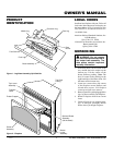
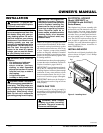
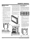
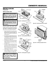
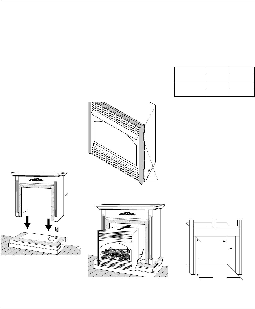
Figure 10 - Installing Cabinet Mantel
Cabinet
Mantel
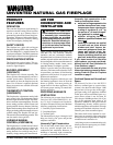
INSTALLATION
Continued
4. Place hearth base accessory against
wall at installation location. Cut an ac-
cess hole in hearth top to run gas line
to fireplace (see Figure 9, page 8).
Make sure to locate access hole so cabi-
net mantel will cover it when installed.
Note:
You can secure base to floor us-
ing wood screws. Countersink screw
heads and putty over.
5. Route gas line through access hole in
hearth base.
6. Center cabinet mantel on hearth base
(see Figure 10). Make sure mantel is
flush against wall.
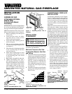
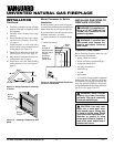
7. Break off nailing flanges (see Figure
11) with hammer or pliers.
8. Place cardboard or other protective
material on top of hearth base. Care-
fully set fireplace on protective mate-
rial, with back of fireplace inside man-
tel opening.
9. If blower is installed, route blower elec-
trical cord through access holes in ei-
ther side of fireplace.
Note:
Bushing
may be moved if necessary. Plug elec-
trical cord into electrical outlet.
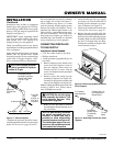
10. Carefully insert fireplace into cabinet
mantel (Figure 12). Be careful not to
scratch or damage hearth base, cabinet
mantel, or any laminate trim on hearth
base. Remove protective material from
top of hearth base and from front of
fireplace (if any).
Note:
You can se-
cure fireplace to hearth or floor. Open
lower louver. Locate screw holes in
bottom of base. Tighten wood screws
through these holes and into hearth or
floor.
11. Attach gas line from fireplace gas regu-
lator to gas supply. See Connecting Fire-
place to Gas Supply, page 11.
12. Check all gas connections for leaks. See
Checking Gas Connections, page 12.
Figure 12 - Inserting Fireplace Into Cabinet
Mantel
Figure 11 - Location of Nailing Flanges
Nailing
Flanges
BUILT-IN FIREPLACE
INSTALLATION
Built-in installation of this fireplace involves
installing fireplace into a framed-in enclo-
sure. This makes the front of fireplace flush
with wall. If installing a mantel above the
fireplace, you must follow the clearances
shown in Figure 16, page 10 . Follow the
instructions below to install the fireplace in
this manner.
Actual Framing
Height 32
3
/
8
" 33"
Front Width 34
5
/
16
" 35
1
/
2
"
Depth 16
11
/
16
" 17
3
/
4
"
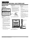
1. Frame in rough opening. Use dimen-
sions shown in Figure 13 for the rough
opening.
If installing in a corner, use dimen-
sions shown in Figure 14, page 10 for
the rough opening. The height is 33"
which is the same as the wall opening
above.
2. If using blower, install and properly
ground GA3555, three-prong 120 volt
electrical outlet, in fireplace. Follow
instructions included in kit.
3. Install gas piping into fireplace loca-
tion. This installation includes an ap-
proved flexible gas line (if allowed by
local codes) after the equipment shutoff
valve. The flexible gas line must be the
last item installed on the gas piping. See
Installing Gas Piping to Fireplace Lo-
cation, pages 10 and 11.
Figure 13 - Rough Opening for Installing
in Wall
Continued
35 1/2"
17 3/4"
33"