


8
107157
UNVENTED NATURAL GAS FIREPLACE
®
For more information, visit www.desatech.com
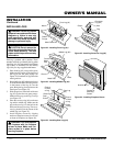
INSTALLATION
CLEARANCES
.5 2
7/16
7/8
1
3
/
4
3
1
/
2
5
1
/
4
7
8
3
/
4
10
1
/
2
12
1
/
4
1 4 6 8 10 12 14 16
FIREBOX
INCHES
INCHES
INSTALLATION
Continued
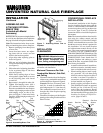
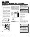
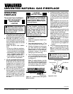
ASSEMBLING AND
ATTACHING OPTIONAL
BRASS TRIM
(Included with Mantel
Accessory)
IMPORTANT:
If you are recessing the firebox
in a wall, do not attach brass trim at this time.
See page 9 for built-in fireplace installation.
Note:
The instructions below show assem-
bling and attaching brass trim to fireplace.
1. Remove packaging from three pieces
of brass trim.
2. Locate four brass screws, two adjust-
ing plates with set screws, and two
shims in the hardware packet.
3. Align shim under adjusting plate as
shown in Figure 6.
4. Slide one end of adjusting plate/shim
in slot on mitered edge of top brass trim
(see Figure 6).
5. Slide other end of adjusting plate/shim
in slot on mitered edge of side brass
trim (see Figure 6).
6. While firmly holding edges of brass
trim together, tighten both set screws
on the adjusting plate with slotted
screwdriver.
7. Repeat steps 1 through 6 for other side.
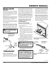
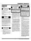
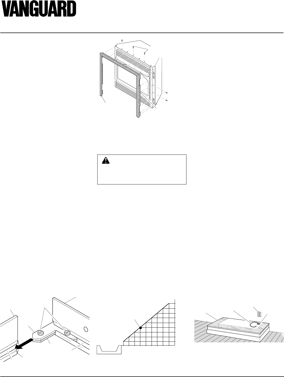
8. Tighten trim hanging screws (#10 x
6.25 shoulder) into holes in cabinets.
Place the assembled trim onto fireplace
cabinet. Align hanging notches on trim
with hanging screws on side of fire-
place (see Figure 7). Push trim firmly
into place, sliding hanging notches over
hanging screws.
Side
Brass
Trim
Top
Brass
Trim
Slot
Mitered Edge
Slot
Shim
Set
Screws
Adjusting
Plate
Figure 6 - Assembling Brass Trim
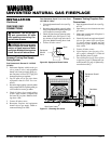
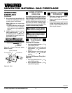
Figure 9 - Placing Hearth Base Accessory
Against Wall
Electrical
Outlet
Hearth
Base
Gas Line
Gas Line
Access
Hole
Note:
The instructions below show installa-
tion using the cabinet mantel and the
G3000F/G3001U/G3004W/G3006F/
G3007U series hearth base accessories. The
hearth base accessory shown is optional for
this installation. You can install fireplace
and cabinet/corner mantel directly on the
floor. The corner mantel accessory cannot
be installed with the G3000F/G3001U/
G3004W/G3006F/G3007U hearth base. The
corner mantel can be paired with the G3008F/
G3009U/G3010F corner hearth base. If
mounting fireplace and cabinet or corner
mantel to the floor, an optional G3005 Slim
Base kit may be installed.
1. Assemble cabinet mantel, hearth base,
and trim accessories. Assembly instruc-
tions are included with each accessory.
2. When installing blower, install a prop-
erly grounded, 120 volt three-prong
electrical outlet at fireplace location if
an outlet is not there. If possible, lo-
cate outlet so cabinet mantel will cover
it when installed (see Figure 9).
3. Install gas piping to fireplace location.
This installation includes an approved
flexible gas line (if allowed by local
codes) after the equipment shutoff
valve. The flexible gas line must be the
last item installed on the gas piping. See
Installing Gas Piping to Fireplace Lo-
cation, pages 10 and 11.
WARNING: Maintain the mini-
mum clearances. If you can, pro-
vide greater clearances from
floor, ceiling, and adjoining wall.
Carefully follow the instructions below. This
will ensure safe installation.
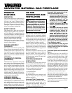
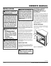
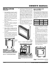
Minimum Clearances For Side
Combustible Material, Side Wall,
and Ceiling
A. Clearances from the side of the fireplace
cabinet to any combustible material and
wall should follow diagram in Figure 8.
Example:
The face of a mantel, book-
shelf, etc. is made of combustible ma-
terial and protrudes 3
1
/2" from the wall.
This combustible material must be 4"
from the side of the fireplace opening
(see Figure 8).
B. Clearances from the top of the fireplace
opening to the ceiling should not be less
than 42 inches.
CONVENTIONAL FIREPLACE
INSTALLATION
Conventional installation of this fireplace
involves installing fireplace along with the
corner or cabinet mantel with hearth base
accessories against a wall in your home (see
Accessories, page 22 and 23). Follow the
instructions below to install the fireplace in
this manner.
Figure 8 - Minimum Clearance for
Combustible to Wall
*Minimum 16 inches from Side Wall
*
Example
Assembled
Brass Trim
Hanging
Notches
on Trim
Trim Hanging
Screws
Figure 7 - Attaching Brass Trim to
Fireplace