


16
104325
COMPACT CLASSIC HEARTH FIREPLACE
VMH26NR
®
OPTIONAL WALL MOUNTED
THERMOSTAT - GWMT1
WARNING: Do not connect
this thermostat to any electrical
source! Electrical shock and/or
fire hazard will occur.
1.
Connect one terminal of 25 ft. wire to
bottom contact of switch (see Figure 31,
page 17).
2. Connect remaining wire terminal to the
“TH” terminal on the control valve.
Make sure that wire terminals are in the
positions on your unit as pictured in
Figure 31 on page 17. If wires are not
“crossed” the thermostat will not work.
3. Route the 25 ft. wire to a convenient
location to mount your thermostat (no
outside wall).
IMPORTANT:
The wire
may be shortened but must not be
lengthened.
The thermostat should be mounted 54"
above the floor in a location where there
is good air circulation. Avoid heat sources
such as lamps, direct sunlight, fireplace,
or heat and air conditioning ducts.
4. Gently remove the cover of the ther-
mostat from the base. Grasp the sides
of the cover firmly and pull to separate
from the base.
5. Feed the electrical wires through the
rectangular slots on each side of the
base (see Figure 32, page 17).
WARNING: Do not connect
the thermostat to a power source.
Electrical shock and/or a fire haz-
ard will occur.
WARNING: Read and follow
installation instructions. Instal-
lation should be done by a quali-
fied installer familiar with low-
voltage wiring procedures.
INSTALLATION
Continued
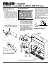
OPTIONAL WIRELESS HAND-
HELD REMOTE CONTROL
ACCESSORIES
(GHRC Series & GHRCT Series)
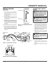
Installing Receiver
1. Remove screws.
2. Disconnect switch wires from the con-
trol valve.
3. Remove switch plate (see Figure 27).
Discard switch plate after removing.
Save the screws.
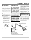
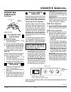
4. Locate the battery clip mounted on the
back of the receiver (see Figure 28).
5. Slide 9-volt battery (not included)
through the clip.
6. Attach the terminal wires to the battery
(see Figure 28).
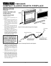
7. Connect wires as shown in Figure 29.
8. Install remote receiver unit onto gas
heater base using the two screws re-
moved in step one (see Figure 29).
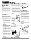
Figure 27 - Switch Plate and Wiring
Harness
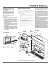
Figure 29 - Installing Remote Receiver
* Wire harness provided in the fireplace
hardware pack.
Heater Base
Screw
Switch Plate
Black Wire
Red Wire
Figure 28 - Attaching Battery to Receiver
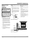
Installing 9-Volt Battery in Hand-
Held Remote Control Unit
1. Remove battery cover on back of re-
mote control unit.
2. Attach terminal wires to the battery (not
included). Place battery into the battery
housing.
3. Replace battery cover onto remote con-
trol unit.
Figure 30 - Installing Battery in Hand-
Held Remote Control Unit
Remote
Receiver
Wires from
Valve
Wire Harness*
Black Wire
Red Wire
Red Wire
Black Wire
Battery
Cover
9-Volt
Battery
Terminal
Wires
Remote
Control Unit
Battery
Housing
Battery Clip
9-Volt Battery
Receiver
Terminal
Wires