


www.desatech.com
105604-01J14
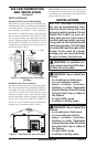
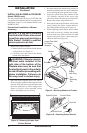
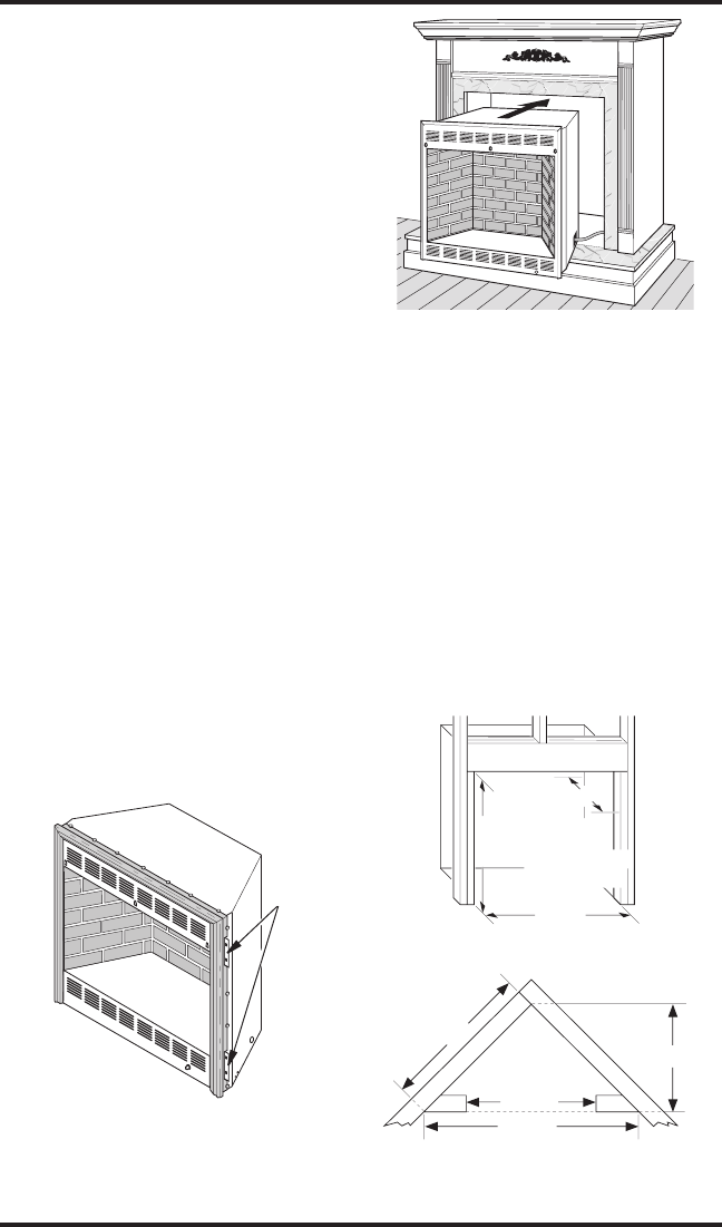
7. Break off nailing flanges (see Figure 19) with
hammer or pliers.
IMPORTANT: When installing Brass Trim
Kit, see instructions included with mantel
accessory.
8. Place cardboard or other protective material
on top of hearth base. Carefully set firebox
on protective material, with back of firebox
inside mantel opening.
9. Attach flexible gas line to log set. See Con
-
necting to Gas Supply in your log set ownerʼs
manual.
10. If installing GA3750A blower (FB32CA
and NLFB32C models only), route blower
electrical cord through bushing included with
blower accessory in right side firebox support
and bushing in side access opening of firebox.
Plug electrical cord into electrical outlet. See
Installing Blower Accessory,
page 10.
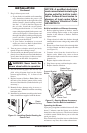
11. Carefully insert firebox into cabinet mantel. Be
careful not to scratch or damage hearth base,
cabinet mantel or any laminate trim on hearth
base. Remove protective material from top of
hearth base and from front of firebox (if any).
See Figure 20.
12.
Install the trim after final finishing and/or
painting of wall. See instructions included with
mantel accessory for attaching brass trim.
13.
Check all gas connections for leaks. See
Checking Gas Connections in log set ownerʼs
manual.
INSTALLATION
Continued
Figure 19 - Location of Nailing Flanges
Nailing
Flanges
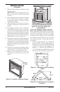
Figure 20 - Inserting Firebox Into
Cabinet Mantel
BUILT-IN FIREBOX INSTALLATION
Built-in installation of this firebox involves install-
ing firebox into a framed-in enclosure. This makes
the front of firebox flush with wall. If installing
a mantel above the firebox, but you must follow
the clearances shown in Figure 7, page 7. Follow
the instructions below to install the firebox in
this manner.
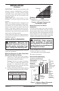
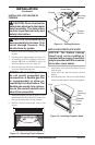
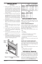
1.
Frame in rough opening. Use dimensions
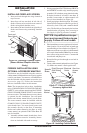
shown in Figure 21 for the rough opening. If
installing in a corner, use dimensions shown
in Figure 22 for the rough opening. The
height is 33" (FB32CA and NLFB32C) or
34
1
/
4
"(FB32NCA and NLFB32NC), which is
the same as the wall opening in Figure 21.
34
3
/
4
"
17
3
/
4
"
33" (FB32CA and
NLFB32CA)
34
1
/
4
" (FB32NCA and
NLFB32NCA)
Figure 21 - Rough Opening for Installing
in Wall
39
3
/8"
27
7
/8"
55
5
/8"
34
3
/4"
Figure 22 - Rough Opening for Installing
in Corner