


www.desatech.com
105604-01J 13
Electrical
Outlet
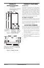
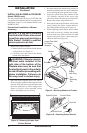
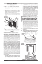
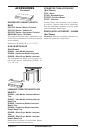
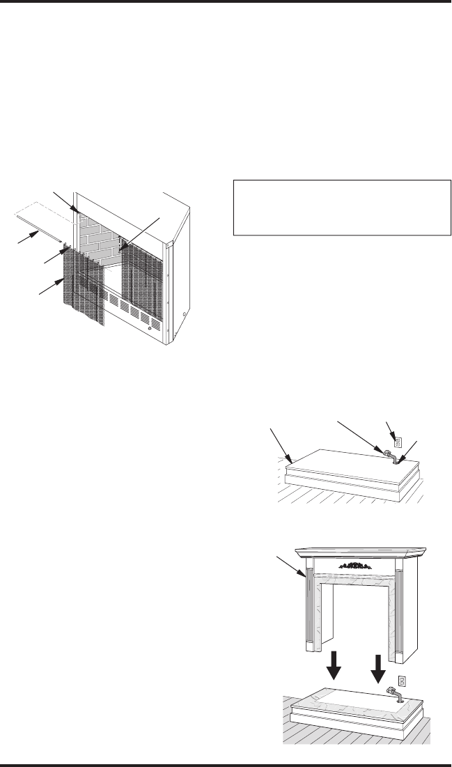
INSTALLING FIREPLACE SCREEN
1. Insert each rod through nine rings located at
top of screen.
2. Insert first rod into rear hole in left side of
firebox. Fasten rod to rear hole near center of
firebox using black shoulder screw.
3. Insert other rod into front hole on right side of
firebox and fasten using remaining shoulder
screw.
Figure 16 - Installing Fireplace Screen
(Shown Without Fireplace Hood for
Clarity)
Rod
Front and
Rear Hole
Ring
Screen
Screw
INSTALLATION
Continued
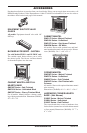
FIREBOX INSTALLATION USING
OPTIONAL ACCESSORY MANTELS
This firebox may be installed using the corner or
cabinet mantel with hearth base accessories against
a wall in your home. You must use a GA6090 brass
trim kit included with the mantel accessories (see
Accessories, page 12). Follow the instructions
below to install the firebox in this manner.
Note: The instructions below show installation
using GM100F/GM101U/GM102W/GM106F/
GM107U series cabinet mantels and the G3000F/
G3001U/G3004W/G3006F/G3007U series hearth
base accessories. The hearth base accessory shown
is optional for this installation. You can install
firebox and cabinet mantel directly on the floor.
The corner mantel cannot be installed with the
G3000F/G3001U/G3004W/G3006F/G3007U
series hearth base. You must install corner and
face mantels directly on the floor. If mounting
firebox and cabinet mantel to the floor or using
corner mantel, an optional G3005 Slim Base kit
may be installed.
1. Assemble cabinet mantel, hearth base, brass
trim and trim accessories. Assembly instruc
-
tions are included with each accessory.
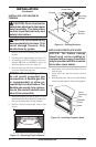
2. If using an optional GA3750A blower (FB32CA
and NLFB32C models only), install a properly
grounded, 120 volt three-prong electrical outlet
at firebox location if an outlet is not there. If
possible, locate outlet so cabinet mantel will
cover it when installed (see Figure 18).
3.
Install gas piping to firebox location. This instal-
lation includes an approved flexible gas line (if
allowed by local codes) and a manual shutoff
valve. The flexible gas line must be the last item
installed on the gas piping. See Connecting to
Gas Supply in your log set ownerʼs manual.
NOTICE: A qualified service per-
son must connect firebox to gas
supply. Follow all local codes.
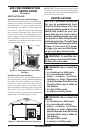
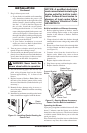
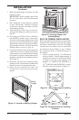
4.
Place hearth base accessory against wall at instal-
lation location. Cut an access hole in hearth top
to run flexible gas line to firebox (see Figure 17).
Make sure to locate access hole so cabinet mantel
will cover it when installed. Note: You can secure
base to floor using wood screws. Countersink
screw heads and putty over.
5. Route flexible gas line through access hole in
hearth base.
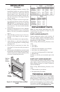
6.
Center cabinet mantel on hearth base (see Figure
18). Make sure mantel is flush against wall.
Figure 18 - Installing Cabinet Mantel
Cabinet
Mantel
Figure 17 - Placing Hearth Base
Accessory Against Wall
Hearth
Base
Gas Line
Access
Hole
Rigid Pipe and
Gas Shutoff
Valve