


www.desatech.com
115121-01B12
ACCESSORy
INSTALLATION
Continued
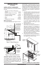
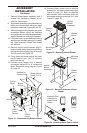
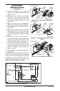
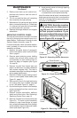
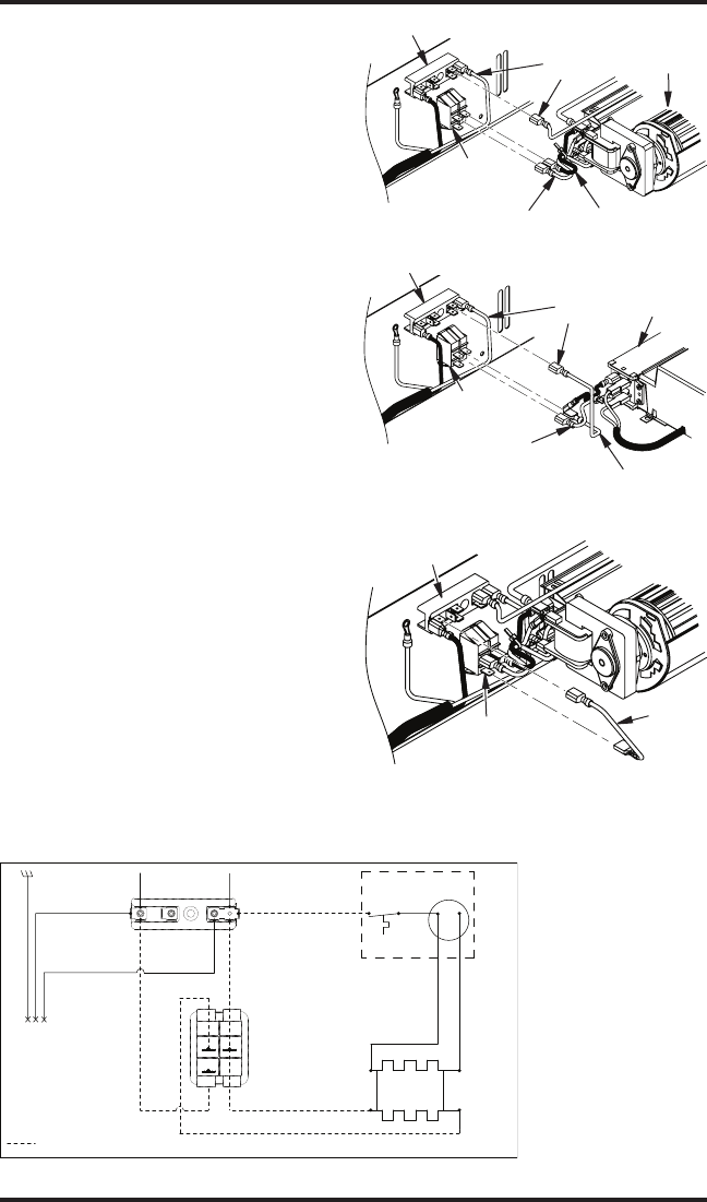
15. Connect red heater wire to terminal
marked 'L-4' on heater power switch (see
Figure 26 or 27.
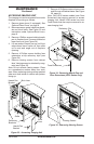
16. Connect one end of black jumper lead,
provided in kit, to power connection
marked 'D' on terminal block and other
end to switch terminal marked 'L-5' (see
Figure 26).
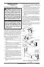
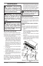
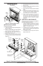
17. Replace 2 hex screws on rear anges of
blower mount removed in step 5, page 10.
18. Remount harness strap to blower mount,
if removed.
19. Make sure all wires are clear of heater
discharge area, line up mounting holes
on front blower mount to holes in control
panels and replace the 2 black pan head
screws.
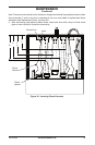
20. Raise control cover up and position 2
locking tabs through notched openings in
rebox top, then slide to left until locked
into position (see Figure 21, page 11).
21. Tuck any excess slack in harnesses into
control cover. Swing cover down to line
up mounting holes on control panel and
replace 2 Phillips screws removed in
step 2, page 10.
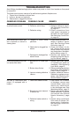
22. Restore power to unit and check operation
of the heater.
IMPORTANT: Be sure to inspect components
and wiring for damage before connecting
power to unit. If any components are found
damaged, contact an authorized dealer for
original DESA replacement parts(s) or call
DESA at 1-866-872-6040 for referral.
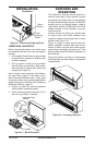
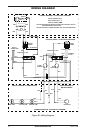
BLK
BLK
TERMINAL
WHT
BLK
GRN
BLK
D C
CONNECTION
SUPPLY
RED
RED
N 1
4 L
5 L
HEATER
COIL
AB
HEATER
POWER
MOTOR
WHT
CUTOUT
WHT
WHT
WIRES TO HEATER CIRCUIT
WHT - ALTERNATE
BLK
HARNESS 4" BLK
Figure 25 - Heater Circuit Diagrams
Rocker
Switch
Red (L-4)
Black (N-1)
Heater/
Blower
White
(A-B)
Terminal Block
Figure 26 - Connecting Heater Wires
Rocker
Switch
Red (L-4)
White (N-1)
Heater/
Blower
White
(A-B)
Terminal Block
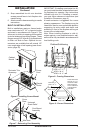
Figure 27 - Connecting Alternate Heater
Wires
Figure 27 - Connecting Jumper Lead
Jumper
Lead
Switch
Terminal (L-5)
Terminal (D)