


USSC 5
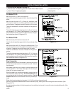
VENTILATION INSTALLATION
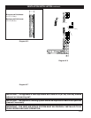
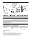
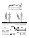
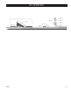
The ventilation system consist of:
1_External Tube - Air incoming tube with enamel hood riveted in place. 1_Threaded Mounting Rod
1_Internal Tube - Outgoing flue gases 1_Adjusting Nut
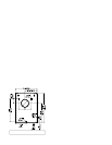
Diagram Nº 3
Diagram Nº 4
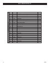
For Model DV12:
Mark the three 5/16” (8mm) holes and drill
Insert the three plastic plugs provided in the previously drilled
holes.
Mark the hole for the 4-1/2” (11.5cm) dia. ventilation tube.
This must be rectilinear and with a slight fall towards the ex-
terior of approx. 2 degrees to avoid the entering of rain water.
Take into consideration the area indicated for the gas con-
nection.
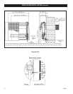
The wall’s thickness cannot be less than 4-1/2” (11.5 cm) nor
can it exceed 13-1/2” (35cm). (See Diagram Nº 5) Tube lengths
and threaded mounting rod should be trimmed to comply to
the dimensions shown in Diagram Nº 3.
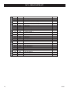
For Model DV20:
Mark the four(4) 5/16” (8mm) holes and drill
Insert the four(4) plastic plugs provided in the previously drilled
holes.
Mark the hole for the 6 1/4” (16cm) dia. ventilation tube. This
must be rectilinear and with a slight fall towards the exterior
of approx. 2 degrees to avoid the entering of rain water.
Take into consideration the area indicated for the gas con-
nection.
The wall’s thickness cannot be less than 4-1/2” (11.5 cm) nor
can it exceed 13-1/2” (35cm). (See Diagram Nº 5) Tube lengths
and threaded mounting rod should be trimmed to comply to
the dimensions shown in Diagram Nº 4.
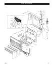
Final Assembly
Remove the front cover of the heater by removing the control
knob and the two(2) screws on the top of the cover. Slide the
front upwards.
After tubes have been cut to length, slide the tubes and the
rod into position on the heater and adjust with the nut pro-
vided until you get a compact unit.
Slide the heater and ventilation assembly through the hole
until the heater reaches the wall. For the model DV12, se-
cure to the wall with the three(3) screws provided. For the
model DV 20, secure to the wall with the four(4) screws pro-
vided.
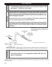
Check that hood protrudes the intended 4 1/4” (10.8 cm) from the exterior wall.
Seal any imperfections between wall and vent hood with putty, making sure that nothing falls inside the hood. (See
Diagram Nº 6)
A protection plate resistant to high temperatures is available at extra cost for use with external combustible walls. (See
Diagram Nº 7)