


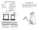

25"
35"
16"
26"
54"
19 1/4"
36"
4 3/4"
NOTE: DASHED LINES SHOW
STRAIGHT UP AND THROUGH
THE WALL INSTALLATION
17"
32 1/4"
16"
FLOOR PROTECTOR
(TOP VIEW)
SIDEWALL
NON-COMBUSTIBLE
CONSTRUCTION IN
ACCORDANCE WITH
NFPA 211
12"
12"
WONDERWOOD
Fig. 2
Fig. 4
Fig. 3
4
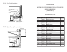
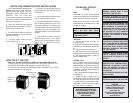
REPAIR PARTS LIST - MODEL 2941 (SEE PAGE 18)
AUTOMATIC WOOD BURNING CIRCULATOR
Key No. Description Qty. Part No.
1 Heat Jacket Assembly 1 68619
2 Base Weldment 1 67859
3 Smoke Curtain 1 22090
* Smoke Curtain Bracket 2 22171
4 Flue Collar 1 40246
5 Flue Collar Gasket 1 88032
6 Draft Damper Frame 1 40075
7 Draft Control Damper 1 23476
8 Draft Damper Hinge Pin 1 17200
9 Clip Spring 1 83818
10 Fire Grate 2 40076
11 Liner 3 40100
12 Firebrick 10 89066
13 Top Brick Retainer 2 40132
Feed Door Assembly 68621
Ash Door Assembly 68620
14 Feed Door 1 40199
15 Ash Door 1 40289
16 Door Latch 2 22108
17 Door Handle 2 40091
18 Feed Door Rope Gasket 3.75FT 88033
19 Ash Door Rope Gasket 2.5FT 88033
20 1/4-20 Kep Nut 2 83250
21 5/16 ID, 3/4 OD Washer 2 83045
22 Latch Spacer 2 21467
23 Door Hinge Pin (Short) 1 83872
24 Door Hinge Pin (Long) 1 23441
25 Heat Shield 1 23475
26 Drop Wooden Handle 1 89523
27 Ash Pan 1 67444
28 Solid Damper 1 D6
29 Top Liner 1 23474
30 Heat Shield 1 22110
31 Secondary Heat Shield 1 22030
* NOT SHOWN
17
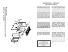
1. The chimney connection should be as airtight as possible. The heater must have its own
chimney flue. Do not connect this unit to a chimney flue serving another appliance. If there
is no chimney near where you wish to place the heater, you can use a UL 103HT Residential
Type and Building Heating Appliance Chimney (Fig. 5, 6, 6A & 6B).
2. Place the heater on solid masonry or solid concrete. When the heater is used on a
combustible floor protector of one layer of 3/8" millboard having a thermal conductivity of
K=0.84 BTU in./ft. 2 hr. Deg. F with 28-gauge sheet metal or a UL Listed floor protector. Have
the floor protector extend 16" beyond the door side of the heater and under the connector pipe
in the back.
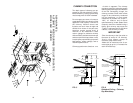
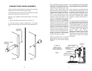
3. Check Figures 2, 3, and 4. Be sure you have the clearances shown from the heater and
the connector pipe to combustible surfaces. If you have a solid brick or stone wall behind your
heater, you can place the heater as close as you wish to the wall. If the wall is only faced with
brick or stone, treat it as a combustible wall.
LOCATING THE HEATER
AS A LOCATION IS SELECTED,
KEEP THE FOLLOWING IN MIND:
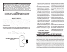
heater or chimney connector. The 1 inch air space provides free air circulation. It is essential that
there be openings at the top and bottom of these clearance reducers so cool air can enter at the
bottom and hot air exit at the top. It is the "chimney effect" whereby when the air in the space is
heated, it rises exiting from the top and being replaced by cooler air at the bottom, that makes these
shields effective.
Masonry, or other non-combustible products, attached directly to a combustible surface without
an air space offer very little protection and cannot be considered a clearance reducer unless
specified materials have been tested and listed for direct attachment to a combustible surface.
The same applies to thin veneer brick and stone coverings. These materials provide adequate
protection only when mounted on sheet metal with a 1 inch spacing to the wall.
A variety or prefabricated clearance reduction systems which have been tested and listed are
available through heater dealers. Always look for a safety listing label on the product when
selecting a clearance reduction system and make sure it is designed for solid fuel appliances. The
manufactures of these systems provide specific installation instructions that must be followed
exactly for a safe installation.