


9
•DRAWINGS FOR ILLUSTRATION PURPOSES ONLY•
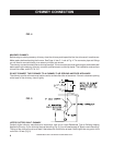
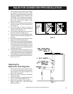
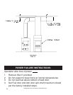
RULES FOR CONNECTOR PIPE INSTALLATION
FIG. 6
The crimped end of the chimney connector
fits inside the furnace flue collar. Install
additional chimney connector and elbow
with the CRIMPED END TOWARD THE
FURNACE. This will allow any condensa-
tion in the flue to run back into the furnace.
Use 6" dia. (minimum 24 gauge) black
chimney connector.
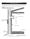
Slope any horizontal pipe upward toward the
chimney at least 1/4 inch for each foot of
horizontal run.
You must have at least 18 inches of
clearance between any horizontal piping
and the ceiling. (See Fig. 3)
The chimney connector must not extend
into the chimney flue (See Fig. 6).
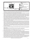
Seal each chimney connector pipe joint with
furnace cement. Also seal the pipe at the
chimney.
Use 3 sheet metal screws at each chimney
pipe joint to make the piping rigid.
The chimney connector may include a sec-
tion for a barometric draft regulator between
the furnace and the chimney (Fig. 4, 5, 6, &
7). The barometric draft regulator must be
installed in the same room (same pressure
zone) as the furnace.
Install the barometric draft regulator strictly
in accordance with the instructions that are
provided with the barometric draft regulator.
A solid damper can be placed between the
barometric draft regulator and the chimney.
(Fig. 4, 5, 6, & 7)
1.
2.
3.
4.
5.
6.
7.
8.
9.
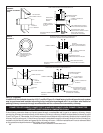
FIG. 7
Adjusting the
Barometric Draft Regulator
Drill a hole in the chimney connector within
18" of the flue collar below the barometric
draft regulator just large enough for the
tube of the manometer.
Build a fire after all chimney connections
have been made.
Use a manometer to measure the draft in
the flue. (U.S. Stove Model DG-26)
Adjust the barometric draft regulator to
obtain a draft of 0.05" - 0.06" W.C. under
stable conditions.
1.
2.
3.
4.