


13
•DRAWINGS FOR ILLUSTRATION PURPOSES ONLY•
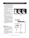
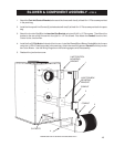
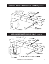
BLOWER & COMPONENT ASSEMBLY - FIG. 9
JUNCTION BOX
MOUNTING
BRACKET
1. Attach the Fan Limit Control Bracket to the rear of the furnace with four(4) of the #10 x 1/2 Tek screws provided
in the parts bag.
2. Install the Honeywell Limit Control (1) to the bracket with two(2) of the #10 x 1/2 Tek screws provided in the parts
bag.
3. Attach the Junction Box(2) to the Junction Box Bracket using two(2) #10 x 1/2 Tek screws. Then Mount the
bracket to the rear of the furnace with four(4) #10 x 1/2 Tek screws. Also Attach the Conduit from the Limit
Control to the Junction Box.
4. Install the five(5) Clip Nuts to the back of the furnace. Install the Blower(3) and Blower Gasket(4) to the furnace
using the 1/4-20 x 3/4 bolts provided in the parts bag. Attach the remaining piece of Conduit from the junction
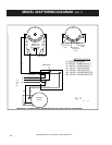
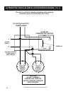
box to the Blower. Use the Wiring Diagram on the following page to wire the assembly.
5. Reattach the junction box cover.
LIMIT CONTROL
MOUNTING
BRACKET
CONDUIT
4
CLIP NUTS
3
2
1
CONDUIT